
SMPS Transformer Live Tester and Servicing CRT TV

This is a CRT TV, in which the board had got damaged beyond repair and I had replaced it with a China kit in July, 2016. During monsoon season CRT TVs tend to develop arcing in the anode cap, due to collection of moisture in the carbon deposit around that area. When the customer reported a hissing noise in the CRT TV, I had advised her to switch off and not to use the TV. But, little will the customers heed to such advice nowadays, as their addiction to serials and other programs in the TV overpower their other essential senses!
As I needed the customer’s help in carrying the TV to work table after cleaning, keeping it outside, it took some time for her to find an amenable auto driver, who was willing to oblige. It was thus that this TV was brought to me on a sunny day along with an aid to assist me. After my opening the TV and cleaning it, he brought the TV to my work table and left. I observed that the anode cap had got punctured.
When I removed the cap, after discharging the anode for any residual charge, I noticed that there was thick growth of fungus not only on the connecting pins, but also in the dip that houses the connector. Cleaned these thoroughly, de-soldered the pin, removed the cap and replaced with a new one. Cleaned the anode area at the CRT thoroughly and made it shine like new. Looked for any dry solder on the board and could not find any. I was happy to have done the preventive retouching of all the points on the board when I fit the board.
Having satisfied that everything else was ok on the board, fit it in, and switched on power. It worked for a minute or two, after which I saw an arcing and loud noise near the sound IC and the MCB got tripped in the electric line. I disconnected the TV immediately and having sensed there are more problems in the board than envisaged, discharged the anode, and removed the board. I saw one fixed green colored capacitor with a value of 0.1mfd (104) near the sound IC had got punctured at its top. I am also giving a circuit diagram of this sound IC, in which I have marked the capacitor that burst.
This was very strange, as no signal was fed and no sound output was there. Checked for any blown or shorting components in the SMPS side and could not find any. Decided to check the voltage output of SMPS, for which I disconnected the resistor going to FBT section, connected a 100W, in its place as load and connected the Multimeter leads for measuring the DC voltage output. When I switched on, the bulb lit for a second and then the fuse blew with a ‘phut’ sound! Checked and found that this time the Switching Transistor which read D5011 was short as well. Once again combed the SMPS area for any shorted or defective components and could not find any. Checked for any defective or shorting components on the secondary side as well. Removed the opto-coupler and checked it using two Multimeters (connect digital Multimeter on ohms range in output and connect the probes of analogue Multimeter, keeping it in X1 Ohms range at the LED side. If we can read a few ohms resistance, the opto is ok.) Please see following pictures:
As all was well and there was nothing that I could trace, replaced the fuse and Transistor and connected it through a series bulb, expecting another failure otherwise. The bulb pulsated showing that nothing was shorting in the SMPS and it is trying to start. So connected the power directly for another ‘BLOOM’ noise with fuse blown. Once again the D5011 failed! I was at a loss to know the reason as I could not find any defect in the circuit. So, another challenge was thrown to me by this TV, this time. I connected an SMPS module after removing the Switching transistor, connecting the Red wire to the Collector input on the board and Black wire to the ground. The output was then ok, indicating that the main winding of transformer and secondary sides were ok. (Since I had explained about use of SMPS module in my earlier articles, I am not repeating it here.
But giving the pictures which are self-explanatory) I suspected that the SMPS transformer, which we call as ‘chopper’ could be causing this problem, as the tapping winding that provides voltage to the primary transistors, after SMPS starts switching, could be partially short. I removed this transformer and tried to fetch a replacement, which is the easiest thing to do. Then removed every transistor and checked it in Peak Atlas and found these to be ok. Removed one end of every component in the power supply primary and feedback circuit and also in secondary and checked it with Multimeter as well as Capacitance meter. Replaced some of the resistors and capacitors, values of which were not exact, though these could not have created the problems. Replaced all the diodes as well . On second thoughts, replaced all the transistors too! Replaced the capacitor that is connected between the hot and cold grounds.
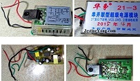
PICTURES OF UNIVERSAL SMPS MODULE:
(Kindly read Jestine Yong’s book on SMPS modification secrets to know further about these)
As the replacement was not available, I made an SMPS Transformer checking system. What I did was taking a universal PCB, and soldering in all components required for the primary, such as input pins, fuse holder, line filter capacitor and coil, rectifier diodes with fixed filter caps and main tank capacitor with bleeding resistor, and make available B+ line and Hot Ground through Thick Red Wire and Black wire. For the secondary, I soldered in four rectifier diodes, with fixed filter capacitor for the secondary High Voltage output and fixed electrolytic capacitors of appropriate value and voltage as seen in any TV SMPS. For example, the primary had 220uF/450V as the Tank Capacitor. For the secondary, I used 100uF/160 for the 110 output and 1000uF/50×3, and provided tapping wires at the input of all these in different colors for easy identification. Then connected the SMPS module which has output voltage adjusting pot on one side. Please see the following pictures, which are self-illustrative:
Connected the removed Chopper Transformer to this tester and applied power. See the result yourselves. Tested a few other transformers that I had and also collected from my friends’ places.
One important point that I want to share with you all, which I learnt from my experiments, is that in the primary the B+ should be given to the main winding at the beginning of winding and return for the Module should be taken from the other. If this is not followed, no output will come! Because in this transformer, the windings have a typical starting and ending points from inner to outer and a particular pattern. It is therefore not equivalent to the AC transformers we see. To check whether the tapping winding in the primary is ok, I connected a rectifier diode and an electrolytic capacitor, as this is the voltage that goes to the SMPS switching circuit after the startup voltage from the input. The voltage was ok. All these transformers were found to be good.
So, I was back to square one. What was wrong in the SMPS that blew the transistor repeatedly! Then my attention turned towards the transistor that I was using. I checked the data online for 2SD5011, and tested a new D5011 in Peak Atlas. I was shocked to see that the D5011 made by Chinese has nothing to do with 2SD5011! The original transistor had one diode and a resistor built in, whereas this D5011 had nothing like that inside! Then I combed the web to know about what is this new D5011, and bumped upon 3DD5011 (a new confusing creation by the Chinese), which is an NPN Transistor with lower voltage limits than the original. The original was rated for 1500V and 10A, whereas this one was not even half of it. Then how did this work so far! Only the God and the Chinese know it (LOL)! In order to make sure that the transistor is the culprit, I connected MD1802FX Transistor, which is better rated and a sturdy transistor. As a precaution, I also connected a one Amp fuse at the ground point of the transistor, removing one jumper wire. I also made ready an overload protector (that is generally used under the Mixies) to connect it in place of Fuse. This is rated for 3A and if the current drawn exceeds, it will disconnect the line. The SMPS worked perfectly! So, I bought another D5011 from a different shop with a different batch number and once again made a suicidal attempt, if I can call it so, with the same failure! So, what is available in the market was complete duplicate stuff! What a waste of time and money! It is unfortunate that there is no law to curtail such malpractices! Following pictures will help you follow better:
So, put back the MD1802FX and tested it once again. See the result yourselves:
Then it was the time for me to find out what preventive steps to be taken to avoid recurrence of failure of this unit. I consulted my friends and they opinioned that since the FBT has suffered severe load arcing for a long time, it is better to replace it and also check all components associated with it. One of my friends told me that the 104 capacitor could have burst due to ground leakage in FBT. Just see the results of values of capacitors that I checked, though ESR checking was ok in appropriate type and values:
As you can see, 220uF showed 153.9, though ESR was ok. The AC filter capacitor, which I had replaced earlier, showed 69.8 in place of 100nF. The 681 cap showed 661, though this variation is not too high. But as it was used in the horizontal section, I replaced it too. The 9.1nF showed 10, which is slightly high, but can be ignored. But I replaced this too, as this is also in the horizontal deflection section. Replaced the FBT with an exact match. And resoldered the resistor to the FBT and connected the Board to CRT.
Switched on, waited for a few minutes and adjusted the screen voltage and focus, and then connected a VCD input. The picture was beautiful:
Adjusted the brightness, contrast, color, sharpness etc. to a pleasing level. Let the TV run for several hours, before finally putting the back cover. Connected the TV to Cable and checked the pictures.
Here are the components that I replaced on the board (You will also find a few electrolytic capacitors that I replaced from the Horizontal section and CRT PCB section as a preventive)
I had mentioned that I collected Chopper transformers from my friends, to get a match. One of my friends, who runs a shop, gave me a new Board, which he had given up repairing due to similar problems. The new board worked only for three months on the TV and he could not trace reasons for repeated failure. He had gone to the extent of replacing even the microcontroller. I checked the power supply section of this board and found a few components that could have caused the trouble. But, people, for whom service is an income for living, cannot spend so much time like me nor can they afford it. So, such swapping of boards is quite common with them. I saw one 222 (.0022uF) capacitor showing half of its value and a voltage adjusting pot not having contact due to rust. Evidently these have been overlooked by my friend!
As you can see, from the top, we cannot suspect the bottom will be so rusted! As the climate in Kerala during monsoon, makes inside of the houses very damp, especially when they are tiled houses, such rust formation is quite common. Moreover, the Kerala is a coastal area. Anyhow, I made the SMPS section working perfectly and kept it aside for any future use, as my friend had already salvaged many other components from the board.
Thus curtain fell to this interesting episode, teaching me new things and refreshing some that I forgot! Only when we get such tough situations, do we get an opportunity to ‘recalibrate’ our brain!
This article was prepared for you by Parasuraman Subramanian from India. He is 68 years old and has more than 30 years’ experience in handling antique equipment like Valve Radio, Amps, Reel Tape Recorders and currently studying latest tech-classes conducted by Kerala State Electronics Technicians’ Association. He has done graduation in BBA degree, private diploma in Radio Engineering and retired as MD of a USA company. Presently working as Consultant to Hospital and other institutions.
Please give a support by clicking on the social buttons below. Your feedback on the post is welcome. Please leave it in the comments.
P.S-If you enjoyed reading this, click here to subscribe to my blog (free subscription). That way, you’ll never miss a post. You can also forward this website link to your friends and colleagues-thanks!
You may check on his previous repair article below:
https://jestineyong.com/servicing-dell-lcd-monitor/
 (90)Dislikes
 (1)
(1)
27 Comments
Leave a Reply


Sheraz
April 3, 2018 at 9:20 pm
dear sir! i have problem while identify the primary, secondry & feedbck winding of SMPS transformer. dear sir what should i do to identify these windings???
Parasuraman
May 6, 2018 at 9:59 pm
The primary winding will usually show some ohms. The feed back winding will usually be independent primary. The secondary winding will be using higher gauge wire and hence it will usually show zero ohms. Use ESR meter for better accuracy.
Robert Calk
April 3, 2018 at 9:46 pm
Nice job, Parasuraman. You don't have a Blue Ring Tester for testing transformers?
Parasuraman
April 4, 2018 at 5:16 pm
Yes, I have, which is assembled by me. I used it too, in the preliminary checking. But did not mention specifically, that's all!
Suranga Electronics
April 3, 2018 at 11:27 pm
Hi.Mr.Parasuraman
Great job. New Thinking Pattern.
R Murali
April 4, 2018 at 1:07 am
Sir, great job. Thanks for sharing.
Lawrence Pina
April 4, 2018 at 3:32 am
I note that you did not use an FBT/LOPT transformer tester on this repair: https://www.flippers.com/fbt-main.html
Would one of these have helped? I bought Bob Parker's original kit from Dick Smith Electronics, Australia, many years ago and have found it to be very useful. It's a real time saver in cases like this...
Thank you for sharing your repair experiences with us. You've got my attention, that's for sure!
Parasuraman
April 4, 2018 at 5:18 pm
Yes, I used. It didn't show any defect. Moreover, it's not full proof.
Albert van Bemmelen
April 4, 2018 at 5:25 am
Impressive repair story Parasuraman. Not something I would try to repeat seeing how many parts needed replacement. And the datasheet of the shown universal SMPS looks interesting. I never use Analogue meters anymore and have a special digital tester for many components including these optocouplers. But I understand that the X1 meter gave power to the led (input side of optocoupler) and a second meter measured the conducting active phototransistor (output side of optocoupler). But I think working with 2 meters and 2 batteries is not the best method to use. My digital tester only needs a single AAA battery and tests almost the full range of TTL and CMOS ICs and quite a few other special semiconductors. And is extremely portable too !See here:
And also this one tests a lot of components including optocouplers!:
Robert Calk
April 4, 2018 at 2:49 pm
If you have a VOM that has the X10k ( added 9V battery = 12V) you can check the phototransistor side. So you only need one meter. I love my BK Precision 114A VOM and wouldn't trade it or sell it. In X10K it is like a 12V insulation tester.
Robert Calk
April 4, 2018 at 10:38 pm
Actually, I like to have all kinds of meters because I love meters and test equipment. If I had the money I would collect all kinds, old and new. Here is some info in support of my glorious VOM: https://www.toolnerds.com/digital-vs-analog-multimeter/
I think we are better off having different kinds of meters and benefiting from them all.
Albert van Bemmelen
April 5, 2018 at 3:30 pm
Like you I now have all kinds of meters Robert. And the last one I recently bought was the ANENG 8002. The nice thing of this portable sized meter is not only that it is a 6000 counts True RMS meter but it also doesn't need a 9V block battery since it operates on two cheaper AAA batteries. Plus it is capable of measuring temperature!
Robert Calk
April 6, 2018 at 11:09 am
Sounds like a good meter.
Albert van Bemmelen
April 6, 2018 at 2:24 pm
Yes and cheap too! Only 11.33 Euro/dollar.
James
April 4, 2018 at 5:13 pm
LoL he works with what he has, but yea', good info Albert.
Parasuraman
April 4, 2018 at 5:24 pm
Many thanks for the suggestions and links. I'm accustomed to reading like this!
Chris
February 10, 2021 at 9:42 am
Albert can you find the last link it seems dead and now I am curious to see the other toy
Bizimungu Jonathan
April 4, 2018 at 8:35 am
hi sir jestine i'm always grateful for your important posts, i hope i will be as a good technician as you,in the future,now i'm reading alot about SMPS,from your books,,,and i hope as well,that i will be as better as you
Jestine Yong
April 5, 2018 at 2:54 pm
Hi Bizimungu,
You are welcome. I have to thank the authors in this blog too for coming out with many kinds of repair tips.
Jestine
James
April 4, 2018 at 5:10 pm
A very good read, thanks for sharing, very interesting indeed.
wills syiem
April 5, 2018 at 3:37 pm
nice job, thanks for your valueable experiences shared to us.
Yogesh Panchal
April 6, 2018 at 3:49 pm
So much Information in article as well comments also thanks everybody.
Ulises Aguilar
April 8, 2018 at 11:49 am
Mr
Parasuraman
grate fix Sir
Humberto
April 11, 2018 at 2:32 am
Good job Parasuraman.
Justice
April 15, 2018 at 8:13 pm
Excellent and highly informative article. Thanks Parasuraman.
lmoudu Onwumah
February 18, 2020 at 6:43 pm
Hi sir
I just come across this article and about a year+ in this blog.This is a remarkable repair.I wish I could do same.
However, at what point on the board was the preventive 3A component soldered.
Blessing Daniel.
February 4, 2022 at 12:47 pm
Gud day sir
Have read true your articles.. And it inspiring..
Am a technician though not very professional... There is this issue i do have with the crt television..
In the smps section the b+ voltage and other voltages from the chopper transformer is present... But the high voltage wont switch ooo.. Sir
Can you please direct me on how to handle such problems.