
TOP 265VG Found Failed In DELL Computer Monitor Model E1715SC

This belonged to the hospital where I work and was admitted to my home hospital for emergency service. The complaint was that the Monitor became dead suddenly. I removed the screws holding the stand and the back cover and pried open to investigate what went wrong.

As visual inspection did not find any bulgy caps or damaged or burnt parts, when I applied power. On checking the power supply board, the 300+ Volt was present which meant that there was no issue in the primary AC/DC supply. Then discharged the cap and checked the SMPS transformer using Ring Tester. I found it to be healthy indicating that there were no shorts either in the primary or secondary. I looked at the datasheet of the switching IC TOP 265VG and checked whether the IC was getting startup voltage and found it to be present. Checked all components in the primary for any short, leak or open. Did the same on the secondary also. Could not find any. ESR of capacitors was also found to be ok.
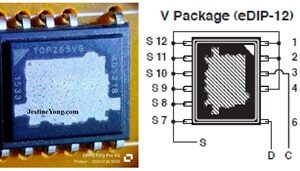
Following is an extract of the datasheet of this crude looking IC along with a picture of the IC. On a sudden look, we might think that the IC is burst. But its design itself was like that!

In order to confirm that the SMPS was indeed working, I removed the IC and connected a three wire Module (Green, Red and Black – Green is not used. Red should be connected to the B+ return point of the SMPS transformer winding and black to the ground.)
As I have explained the use of this module several times in my various articles, I am skipping it in this article. (Those who still want to know, may please read this article: https://jestineyong.com/cracked-unknown-pwm-replaced-by-universal-module-in-pressure-monitor-smps/ I kept the potentiometer at the minimum and applied power.

The outputs were present. Then removed the module and connected a four wire module (5 to 24V module) the use of which was also explained by me in my previous articles. As a precaution, I replaced the opto IC 817 and feedback control IC TL431, after ensuring that the surrounding components were ok. (For those who might have missed:
https://jestineyong.com/a-five-wire-str-module-did-not-work-in-this-aoc-lcd-monitor-model-tft15w60ps/) The advantage of this module is that we can check the feedback circuit and proper switching function unlike the three wire module. The 3 wire module can withstand any shorts in the secondary, whereas the four wire module (5-24V module as it is called) might succumb to such shocks. That’s why I used this method. Then the desired voltages were present.

So, I ordered for replacement of the IC. Got it the next day and removed the module and soldered the IC in its place.
Then when I powered the monitor on after connecting the mother board and panel, it was found working very well. I fed a signal from the pattern generator. After allowing the monitor to be in on conditions for sufficient time, I fixed the covers and once again left it on for a very long time as a part of ageing test. It was found working very well, pulling the curtain down on this repair job, before which the satisfaction jumped into the bag.


This article was prepared for you by Parasuraman Subramanian from India. He is 74 years old and has more than 30 years’ experience in handling antique equipment like Valve Radio, Amps, Reel Tape Recorders and currently studying latest tech-classes conducted by Kerala State Electronics Technicians’ Association. He has done graduation in BBA degree, private diploma in Radio Engineering and retired as MD of a USA company. Presently working as Consultant to Hospital and other institutions.
Please give a support by clicking on the social buttons below. Your feedback on the post is welcome. Please leave it in the comments.
P.S-If you enjoyed reading this, click here to subscribe to my blog (free subscription). That way, you’ll never miss a post. You can also forward this website link to your friends and colleagues-thanks!
You may check on his previous article on Interesting Repair Story Of A Sharp DVD Player Model DV-SL1000W
 (37)Dislikes
 (1)
(1)
11 Comments
Leave a Reply


Waleed Rishmawi
August 30, 2025 at 4:32 pm
a very nice dedective work there my friend. by the way every time you mention hospital in the begining of the article I know it is you...LOL. loved the article. have a blessed day mny friend.
Parasuraman S
August 30, 2025 at 8:00 pm
In a sense, this hospital service might perhaps be responsible for not getting admitted there! (LOL) Many thanks, dear friend!
Albert van Bemmelen
August 30, 2025 at 4:43 pm
It always is remarkable how easy you make use of those 3 and 4 wire power Modules for testing any smps! So thanks again for showing another example of this method with the added links to show all necessary information.
Parasuraman S
August 30, 2025 at 8:00 pm
Yes, when technology advances, we have to make use of it to ease our troubleshooting methods! Many thanks, dear Albert!
Yogesh Panchal
August 30, 2025 at 6:25 pm
you are lucky to get this IC Sir,
have you ever tried any of this module in ATX SMPS
Parasuraman S
August 30, 2025 at 8:02 pm
We can do it only for the primary switching if it uses an IC. Many thanks, dear Yogesh Bai!
Mark J
August 31, 2025 at 4:14 am
Parasuraman another great repair job. You always like your smps repair articles.
Mark J
August 31, 2025 at 4:15 am
Sorry I made a typo. I meant to say I always like your smps repair articles.
Parasuraman S
August 31, 2025 at 6:21 pm
Does not matter! That too was correct! Many thanks, dear Mark!
Imoudu O
August 31, 2025 at 5:28 am
If I may know,for what factor was the green wire of module was not connected to original board since it has opto ic on it.
Parasuraman S
August 31, 2025 at 6:24 pm
The green wire actually is to be connected as a feedback sense. But in our experience that does not work properly and the switching reaches saturation causing high voltage that would damage the PS sometimes beyond repair. It also needs modification of the feedback circuit suitable to that circuit. So, the safe way is not to connect it as it works well even otherwise, at-least for testing. Many thanks, dear!