
Build Your Own Capacitor Discharge Probe
In another post the subject of how to safely discharge ecaps, A/C start caps, microwave oven caps and even 2nd anode leads on CRT type TV’s was raised.
You should NOT short the leads of a cap to discharge it. There are 3 good reasons not to do this. First it is dangerous since much energy can be stored in a capacitor, enough to give you a serious jolt or burn your skin. Second, the capacitor can be damaged because of the high current pulse that can take place within the capacitor. Third you will usually pit or possibly ruin the screwdriver you use to short the terminals.
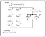
Discharge the high value main filter capacitors in TVs, video monitors; switchmode power supplies (SMPS), microwave oven capacitors, and other similar devices quickly and safely. Use the following circuit to safely discharge capacitors.

D1-8 are 1N4000 series silicon rectifiers or similar.
These diodes raise the junction of R1 about 3v off ground.
This permits the indicator LEDs to light. LEDs are any type without internal resistor.
R1 is 2K ohms for Low Voltage (up to 450 volts)
For Microwave ( 5000 v caps ) ovens use 100K ohms
For TV 2nd anodes use 1 Megohm.
2 Watt resistors should be adequate since current will flow for a short period of time.
R2 is 100 ohms ½ watt and limits the current to the LEDs.
2 LEDS are used to indicate the potential remaining regardless of polarity. When they go out it indicates the cap is fully discharged. Be sure probe is well insulated. A plastic, vinyl or other insulating tube should house the probe. You could place the resistor inside the tube and use a short length of #14 solid wire as a probe end. The whole circuit could be placed inside a plastic tube for safety. Be sure to solder all connections and be sure the ground clip is also insulated. If it comes off the ground point while you are discharging, the full cap voltage will appear on the ground clip. Ouch!
For ground remember to use the same ground point that the capacitor being discharged uses.

This article was prepared for you by George Persico from USA. He is 66 years old and has more than 40 years’ experience in TV repair both Tube and Flat Screen. He also currently repairs small appliances, battery operated tools and computers.
Please give a support by clicking on the social buttons below. Your feedback on the post is welcome. Please leave it in the comments.
P.S- If you enjoyed reading this, click here to subscribe to my blog (free subscription). That way, you’ll never miss a post. You can also forward this website link to your friends and colleagues-thanks!
Note: You can check his previous repair article in the below link:
https://www.jestineyong.com/repair-of-amana-goodman-hotel-air-conditioning-control-board/
 (179)Dislikes
 (3)
(3)
23 Comments
Leave a Reply


Brent Blosfield
January 13, 2016 at 10:16 am
Great article thank you George and Jestine!!
Jo
January 14, 2016 at 11:08 am
To discharge (3) values or R1 would be a pain, so you would have to build (3) tubes marked with the (3) values ! Any suggestions ?
Gregor
January 13, 2016 at 10:47 am
Great article ... very useful ... thank you for posting & sharing your knowledge!
skwong
January 13, 2016 at 11:30 am
Brilliant design which is cheap, safe and easy way of discharging capacitor.
Yogesh Panchal
January 13, 2016 at 2:42 pm
Sir,
Thanks for informative tips.
Hermann
January 13, 2016 at 5:36 pm
I've built this tool a while ago. It is working well. I also added a buzzer so that I don't have to watch the LEDs patiently all the time.
Albert van Bemmelen
January 13, 2016 at 7:24 pm
Thank you George. If someone in his daily job has to constantly discharge Capacitors it will be a great tool!
Paulo Brites
January 13, 2016 at 7:42 pm
Great idea George I just used to do some resistor I have in hand but the idea of LEDS is pretty good chiefly for thoses that are beginning.
I would like to issue the circuit in my web page given the credits for you of course.
I will appreciate your agreement.
Tks
Paulo Brites
George Persico
January 16, 2016 at 8:31 am
Permission given to use on your web page. Credit Jestine Yong so techs get back to here and learn more. George
Andre
January 13, 2016 at 8:46 pm
Thanks for the great article George... Can this work on a 40,000 VDC pulse? What I mean is, I use an equipment that generates 40,000 volts and I want to use this to measure the voltage that come out of the equipment with the probe and a oscilloscope. Can this be done?
George Persico
January 16, 2016 at 8:52 am
Andre
This probe is designed to bleed away the charge on a capacitor, not to measure it. To measure 40,000 vdc you would need to construct a voltage divider using a very large value resistor at the top of the divider and a small (relatively speaking) resistor at the bottom to measure across.
If you do this often you should invest in a commercially constructed probe which can be safely used with your DVM. At 40Kvdc strange things can happen like conducting film on the surface if resistors. Mistakes can be costly. If any significant current is available mistakes can be deadly.
Robert Calk
January 13, 2016 at 11:17 pm
Thanks George. Nice tool.
Parasuraman S
January 14, 2016 at 12:49 am
A very useful article! Very nice of you to have shared this!
Erik
January 14, 2016 at 12:58 am
Hello Hermann, can you tel me where you put the buzzer on.
thanks
Andrew F. Ali
January 14, 2016 at 5:53 am
Nice tool for the beginner. I personally have been using a 1k 2W resistor across the e-cap successfully for many years now and have had no problems like accidentally shocking myself.
Allan
January 15, 2016 at 1:56 am
Hi George, what a cool capacitor tool. I sure love this article, great stuff and thanks for sharing.
Maurizio C.
January 15, 2016 at 8:49 am
Thanks! I look forward to buying one (patented) piece on the web soon!
Tyrone
January 15, 2016 at 8:47 pm
Very good tool George.
Hicham
January 17, 2016 at 5:17 pm
Following Jestine technics that i learn from before was to place around 1.8 to 2kohms, basicaly your tool seems to be correct enough with leds indication, thank you George, good job making out a usefull tool.
NAKUDO ROBERT.
April 8, 2016 at 12:40 am
Thanks for sharing with us such a good innovation, may God bless you.
Reniel Silva
November 3, 2016 at 11:44 am
Thank You for this article! Can you post a picture of your probe?
jon
February 16, 2018 at 9:30 am
Great little circuit. May i suggest, Why not put the 3 resistors in and add a 3 way switch to choose between the 3 depending on what your discharging ? I will go ahead and build myself one of these discharge tools using the 3 resistors and a switch (labelled).
Nawual
April 26, 2018 at 5:21 pm
Hi, good idea the switch with 3 position.¿which can i use for this?