
Bypassed A Burnt Connector In LG LED TV 22LN4100-TA
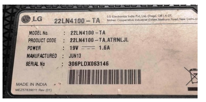
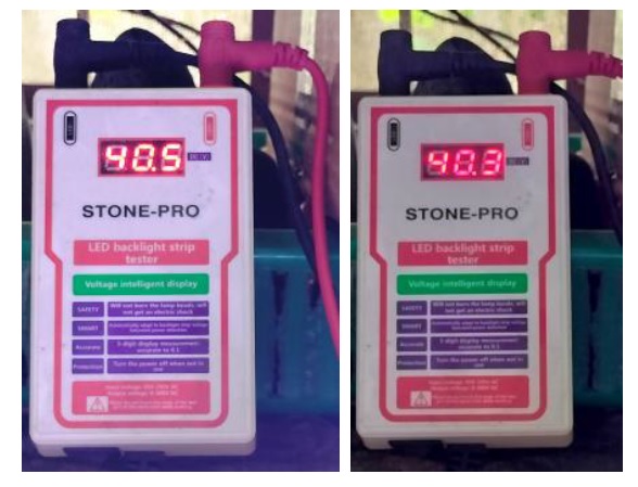
This LED TV belonged to a regular customer and he brought it to me with the complaint that the display failed while watching. He reported that there was a power surge too at that time, as the lights and fans flickered. I opened the TV by removing its stand fixed with two screws and prying the sides. I applied power and checked for LED driver voltage, which was found to be 24.5V, indicating that the driver was working, but not boosting, in the absence of any load.
There were three strip cables going to the scaler board in this TV. One was the data connection to the Panel and the other was the combined power supply to the scaler. The third one was the LED Driver cable. Then I removed the LED strip cable and checked. It had burnt marks. Since the connector is fixed on the scaler board, I did not want to risk removing it, as no replacement connector was available in the market. Then I dismantled the TV to check the condition of the cables on the Edge Led strip side. Following are a few helping pictures to ensure that you are with me in the narration:
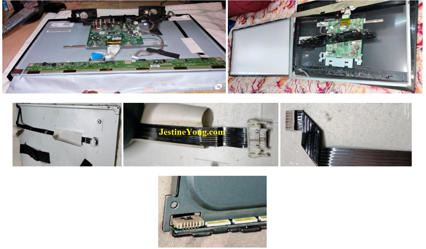
Then I used my LED Checker to test the LEDs. The connector had 7 pins. Out of this the ones at both ends were the negative connections controlled by the LED Driver IC. The centre two pins are fed the + DC voltages required. The other two pins adjacent to the negative lines are dummies.
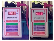
I kept the + probe in the centre and minus probe on one side of the connector and got a reading of 40 V with the LEDs brightly lighting up. The LED strips had 28 LEDs with 14 LEDs connected in series. Did the same with the other side too.

Having ensured that the LEDs were healthy, I reassembled the panel. Then cleaned and inserted the cable on the LED side and provided bypass wires for LED1 & LED2 to the sides of the scalar end of the connector, with the DC supply going to the two pins in the centre. I peeled off the dummies so that it does not cause a short by catching the solder. I also rechecked the connections from that end of the cable using the LED checker and it was found ok. Following is the picture that would show you how it was connected:

Then interconnected the boards with its appropriate strips and applied power. The TV came on with display, upon which I applied Fevibond (Rubber compound) on the connections to ensure that these stay put. I fixed a few more tapes on the metal body of the rear side of panel to isolate the wire and again applied gum for keeping it safe from any arcing. The job was done after a lot of efforts as the soldering required precision and recheck for proper contact to avoid any shorts. The TV was tested for several hours on two days, before offering it to customer. Thus Mission got accomplished with intense satisfaction getting collected into the coffer.
Those of you, who are accustomed to digging me for not getting a chance to replace all electrolytic caps, can have a free go! (LOL)


This article was prepared for you by Parasuraman Subramanian from India. He is 74 years old and has more than 30 years’ experience in handling antique equipment like Valve Radio, Amps, Reel Tape Recorders and currently studying latest tech-classes conducted by Kerala State Electronics Technicians’ Association. He has done graduation in BBA degree, private diploma in Radio Engineering and retired as MD of a USA company. Presently working as Consultant to Hospital and other institutions.
Please give a support by clicking on the social buttons below. Your feedback on the post is welcome. Please leave it in the comments.
P.S-If you enjoyed reading this, click here to subscribe to my blog (free subscription). That way, you’ll never miss a post. You can also forward this website link to your friends and colleagues-thanks!
You may check on his previous article on Restored USB Room Humidifier
 (42)Dislikes
 (0)
(0)
10 Comments
Leave a Reply


Albert van Bemmelen
June 15, 2024 at 7:51 pm
Good job! Hopefully the long thin wires stay in place and don't burn through.
Google says => 0.1mm is roughly 38 AWG. So for that, for "chassis" wiring (i.e., short runs between boards, switches, lights, etc) the current limit is 130mA. For longer "power" runs, the limit is a mere 22.8mA. The resistance of the wire is around 659.6Ω per 1000 feet, so about 0.659Ω per foot.
The rule is that an increment of 3 in AWG numbers represents a halving of the cross-sectional area of a wire and not much current can pass through.
Parasuraman S
June 15, 2024 at 9:10 pm
Many thanks for your comments and sharing a very valuable information on guage of wires and its implications.
Yogesh Panchal
June 15, 2024 at 10:52 pm
Good Job! Sir
try to use UV curable Solder mask on jumper wires for extra protection.
Parasuraman S
June 16, 2024 at 4:16 pm
Many thanks for your advice and comments!
Philip
June 16, 2024 at 12:08 pm
Thanks Parasuraman & Albert. The general working principle of a tv electronic circuit is that the SMPS has components like a fuse, varistor, chokes, diodes, optoisolator and indeed the always talked about capacitors, all these help to provide power and also help to prevent the secondary section from a power surge destruction. But as the SMPS seems to have been left unattended despite the general rule. weakened components by the surge rage are likely still lying in the whole circuit
Parasuraman S
June 16, 2024 at 4:17 pm
Many thanks for your comments and sharing of expert experience.
Imoudu.O
June 17, 2024 at 4:28 am
Thanks for well explained bypassed repairs relating to backlight, i caught some knowledge.
Parasuraman S
June 17, 2024 at 3:41 pm
Many thanks for your comments! Glad to note that it helped you!
Waleed Rishmawi
June 17, 2024 at 1:58 pm
as always, a job well done and the TV is alive and kicking..lol. thanks for sharing and have a blessed day. I share the same concern about the gauge of the wire used but it should hold for a while I hope. have a blessed day
Parasuraman S
June 17, 2024 at 3:42 pm
Many thanks! I have done this type of wiring in scalar boards and backlights. It stays put.