
Clicking Noise in Computer ATX SMPS
Received ATX SMPS (Circle- Model CPH699-400) for repair with problem it turns off after one clicking noise. Opened the SMPS for inspection on visual testing I found everything is OK there was no physical damage or burning marks.

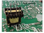
I have removed the circuit out of chassis for testing I connected to power and turned ON. I can see spark with click noise near driver transformer ……
Above photo- clicking sound and spark happened for a split of second and the power supply shutdown
I have connected series bulb but there was no sign of shorting on starting. After click spark it went to protection mode so I am unable to do any voltage testing.
So I have checked every component by removing one by one.
I did not found any burning marks or any physical damage.
I am having doubt on PWM IC and Supervisor IC but I did not found any datasheet for these two ICs.
It is very difficult to trace the circuit without exact schematic diagram hence put this case on hold.
Need your comments for this problem if anybody is having detail / equivalent replacement of these parts……..
This article was prepared for you by Yogesh Panchal who works as a Computer Hardware Engineer in Mumbai India.
P.S- Do you know of any your friends who would benefit from this content that you are reading now? If so, forward this website to your friends or you can invite your friends to subscribe to my newsletter for free in this Link.
Note: You can check his previous repair articles in the link below:
https://jestineyong.com/dell-inspiron-laptop-intermittent-power-problem-repaired/
 (44)Dislikes
 (0)
(0)
18 Comments
Leave a Reply


Albert van Bemmelen
April 15, 2021 at 2:23 pm
I have saved lots of defect smps power boards with all kinds of transformers on them. One of those driver transformers will be used soon to drive my +100V DC generator in a famous Jim William's avalanche pulse generator that acts as a Picosecond Fast Rise pulse generator. With this DIY tool we can easily establish with good estimate the bandwidth of any oscilloscope! I need it to calibrate the external adjustments in my Tektronix 2440 oscilloscope. See for instance this link on hackaday:
Albert van Bemmelen
April 16, 2021 at 2:45 pm
PS: here some info about the pinconfiguration of the SR6110B => https://grabcad.com/library/fonte-atx-500w-sr6110bx16-1
Yogesh Panchal
April 16, 2021 at 10:55 pm
Albert, Thanks! for providing Lead.
Here i found exact equivalent IC......
http://www.datasheetcafe.com/sdc2921-datasheet-pwm-controller/
Yogesh Panchal
April 16, 2021 at 11:05 pm
Albert,
Failure rate of these kind of transformers are less then 1% and that also because of bad quality of insulation (Varnish Type) coating used on the wire in transformer.I have also salvaged this transformer for using Wire in various other use.
Albert van Bemmelen
April 17, 2021 at 1:54 pm
Understood Yogesh, I hope you will be able to find the culprit with the info in above given link. It also shows how to make a adjustable ATX SMPS powersupply and it looks like that the SR6110B chip is equivalent to a 7502B controller? Like you I also salvage wire, also very thin wire from relay coils and the thick copper wire from the deflection coil of crt TVs and of the demagnetize coil. The thin relay coil wire is always handy in various repairs.
Albert van Bemmelen
April 17, 2021 at 1:58 pm
https://datasheetspdf.com/pdf-file/684442/EST/EST7502B/1
Yogesh Panchal
April 17, 2021 at 3:29 pm
Thanks! Albert,
This is exact Replacement..............
Jaikumar Bidkar
April 19, 2021 at 4:30 am
Try 4 pins STR 5LO380R,
REMOVE 7 PIN IC You showing in last pics with red circle,
Just hook up 5L0380R
Pin 1 GND
pin 2 Hot (310v via TFR.
winding )
Pin 3 Vcc (connect 220k/1w.
Resistor from
+310V.& +Ve supply
From AUX. WINDING
(diode's +Ve side)
Pin 4 FEED BACK FROM OPTO
COUPLER pin 4 /
Ground pin 3 of
OPTO coupler
This will help you to clears
+5volt & +12volt (Stand by & Osc.voltages)
Albert van Bemmelen
April 17, 2021 at 2:10 pm
Here another very small Jim Willams Picosecond pulser. The small pcb can be ordered in one order of 3 identical dual layer boards for just about US$6.65 free shipping (about 21 days delivery).See => https://oshpark.com/shared_projects/KrhgN8JM
and more info here. I believe that version 2.4 with date march 2021 was the latest version. (previous versions were also v2.4 but with older dates!)
Albert van Bemmelen
April 17, 2021 at 3:21 pm
oops: Most recent upgrade was v2.4 from the year 2017! So not 2021.
Albert van Bemmelen
April 17, 2021 at 4:49 pm
Interesting fact!: Know that these Picosecond 'avalanche' superfast rise pulse generators also can be used in coax dsr measuring situations. See for instance these videos on that subject =>
https://www.youtube.com/watch?v=I1gfUNh5PJQ
https://www.youtube.com/watch?v=Il_eju4D_TM
https://www.youtube.com/watch?v=F-ZDiGmLvTs&t=4s
https://www.youtube.com/watch?v=8il3AGUkMM4
Calin
April 15, 2021 at 3:35 pm
I don't know if it helps but I had a problem similar to a CRT TV a few years ago. I started from the remote control, the led from stby changed to green for a few seconds after which a click was heard, the led changed back to red and ... nothing. I found at one of the voltages (3.3v) the electrolytic capacitor in short. I changed it and it worked. I say this if you haven't checked the electrolytic capacitors.
Yogesh Panchal
April 16, 2021 at 11:10 pm
Calin ,
Thanks!for your Comment, as i said in article i have checked every parts on PCB Other then those two IC's, may be possible some part is misbehave under load...
Parasuraman Subramanian
April 15, 2021 at 4:55 pm
Change all electrolytic capacitors. I am sure you would have retouched all solder joints. Change the TL431 and optocoupler. Check for value changes, especially the resistors. Try dropping the drive using resistors.
Yogesh Panchal
April 16, 2021 at 11:15 pm
Sir,
I am having 85% doubt on JD3313D IC Because this IC is directly involved in switching.....But i will try your idea for changing Capacitors.
Marco
April 15, 2021 at 8:18 pm
The second chip is from JDsemi ( http://www.jdsemi.cn/en/jcdl.asp?Pid=31&page=4 )
You can try to contact them and ask for datasheets (link is broken on their website)
I think you can try also to draw yourself the circuit, it's not so hard on single layer PCB boards like SMPS.
Regards,
Marco
Yogesh Panchal
April 16, 2021 at 11:23 pm
Marco,
I tried on web site but link does not show any detail.
As per your advice i Emailed them a request for the Datasheet.
for drawing circuit it is bit time consuming right now i put it on hold till finish some urgent pending jobs.
hesham farouk
December 28, 2022 at 5:27 pm
using my email heshamfarouk370@gmail.com
i need datasheet jd3313d or equivalent
not found this ic in market in egypt