
Conventional Method Employed Had To Be Reverted In IKON Induction Cooker Service

This induction cooker was brought to me by a regular customer stating that it belonged to his neighbor and it was lying unused for a long time. As usual, after finishing my opening and cleaning up inside out, I brought the PCB to work table for scrutiny. I had already noticed that the fuse had cracked, indicating that IGBT would have definitely blown along with some other in the power supply.
Checked and found that the IGBT was indeed shorted. As a routine maintenance, I replaced all the 8050/8550 transistors, 78L05 and 18V Zener and all the high watt resistors. I did not replace the IGBT at that stage. Did a resoldering touch of all points on the PCB. Looked for any defective components such as diodes, other resistors etc. Then replaced all the switches on the panel, as these were found to be defective and rusted.
As you will notice, the high watt resistors were replaced by two resistors in series as exact replacements were not available. All these were 200K resistors. But these are not available in the market. So, used two 100k resistors in series and covered it with sleeves applying Fevibond (Rubber Compound) for protection. The Fan was rusted and stuck. So, replaced that too.
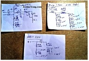
Then when I applied power, there was continuous beep which looked like an error indication. This cooker was not having any display. So, no error message could be read. Anyhow, as the fan was running, and voltages were normal at 5V and 18V Zener, I replaced the IGBT and applied power, after reconnecting the coil and placing the vessel on its top cover. The beep continued without any heating up. Checked the voltages at each stage and I got the result as below:
Then what was wrong? I had no clue! When I checked with my techie friends, one of them told me that the 200K resistors were of 1% tolerance, whereas the 100K resistors (two each for one 200K) were all of 5% tolerance. So, he advised me to put back the original resistors and try. As the removed resistors were showing the reading correctly, I removed the replaced resistors and put the original back. This time the Induction Cooker worked very well without any error beeps!
So, a lesson learnt. Though I had done such replacements in several Induction Cookers, this was the first time, I got snubbed! Probably the circuit was designed and programmed in such a way that even a slight variation in the voltage would be sensed and working deactivated. I tried the cooker for a few days in my kitchen and found it to be working very well. In fact, cooking was faster than the one we used in the kitchen.
Here are the pictures of the defective components and the resistors and sleeves which I took back:
Anyhow satisfaction did not feel ashamed to jump into its collection bag (perhaps with a snubbed nose this time! (LOL)
This article was prepared for you by Parasuraman Subramanian from India. He is 72 years old and has more than 30 years’ experience in handling antique equipment like Valve Radio, Amps, Reel Tape Recorders and currently studying latest tech-classes conducted by Kerala State Electronics Technicians’ Association. He has done graduation in BBA degree, private diploma in Radio Engineering and retired as MD of a USA company. Presently working as Consultant to Hospital and other institutions.
Please give a support by clicking on the social buttons below. Your feedback on the post is welcome. Please leave it in the comments.
P.S-If you enjoyed reading this, click here to subscribe to my blog (free subscription). That way, you’ll never miss a post. You can also forward this website link to your friends and colleagues-thanks!
You may check on his previous article on Denon AVR-X500 Repair
 (46)Dislikes
 (0)
(0)
14 Comments
Leave a Reply


JOHN
June 4, 2021 at 9:01 am
I wish we could expand the pictures to see exactly what you are talking about in the aricles.
Parasuraman S
June 4, 2021 at 6:14 pm
Yes, something we should be able to do. But, I have never tried. Someone who tried or Mr.Jestine Yong himself might guide us! Many thanks for your comments!
Jestine Yong
June 5, 2021 at 12:44 pm
Hi John,
Try press on the Ctrl key and scroll the mouse, the screen will become bigger.
Jestine
Parasuraman Subramanian
June 6, 2021 at 4:33 pm
Oh! Great! I never knew! Shall try!
Albert van Bemmelen
June 4, 2021 at 1:08 pm
If I noticed it on the photo correctly, you also have tried many other 100K 5% resistors in serie to check for a working 200K 1% sensor resistor replacement? But when only replacing the original 200K 1% resistor worked I guess it must still have been possible to measure that right original value too? I understand that the tolerance made it impossible to make a replacement in two 5% 100K resistors in serie. But by also measuring those and writing those values in a list it would have been clear what exact deviation caused the unexpected problem. And likely would have proven that fact in irrefutable results.
Parasuraman S
June 4, 2021 at 6:18 pm
Voltages are measured after it gets on. But uController checks voltages in microseconds and shuts off if it does not match with the set limit. I could not find much difference in the value of the voltages. Anyhow, you have put in a lot new points to ponder over. Many thanks for your comments!
Paris Azis
June 5, 2021 at 4:10 pm
Albert, the tolerance of resistors in some circuits is very critical indeed. The tricky point with it is that when connecting resistors in series, the worst case scenario for this case specifically can be a 10% drift of the total value, as the individual tolerances of these resistors add up. Of course the inverse happens when they are connected in parallel. Therefore, in such a need, the parallel connection is the preferable one, depending on the availability of proper resistors of course, as it results in total tolerance improvement.
Apart from these above, there is another factor to be taken into account. If the processor measures somehow both the DC and AC voltage components through the resistive divider, then this (originally metal film, i guess) resistor cannot be replaced by wire wound resistors. The reason is the inductance factor they introduce. No matter how small it can be, it works as a choke for the high frequency pulses used for the operation of such equipment. Therefore if a circuit is responsible to measure their magnitude cannot "see" them, then a problem is already there...
That's why I always insist and suggest everyone: never do wholesale replacements in blind (without prior measurements). It's the best way for causing chaos latter on...Always go step by step and check each time your previous step before the following one...
Albert van Bemmelen
June 6, 2021 at 12:54 pm
Your experience in these matters is extraordinary Paris! I recently read while finishing a new Jim Williams Avalanche pulse generator that the ringing in a signal caused by a choke (coil) can be limited by simply placing two higher ohmic resistors in parallel over it. Discrepancies that easily occur at square waves at higher frequencies. Since the ideal square wave contains only components of many odd-integer harmonic frequencies (of the form 2π(2k − 1)f). Sawtooth waves and real-world signals contain all integer harmonics. Which becomes a quite complex theory even though the signals look so simpel!
Parasuraman Subramanian
June 6, 2021 at 4:37 pm
Vow! Learning new things from you all! Great!
Parasuraman Subramanian
June 6, 2021 at 4:35 pm
Very informative!
Waleed Rishmawi
June 4, 2021 at 2:42 pm
so you soldered the resistance off board then you used it again? you do not check before removing? but I am glad it worked out. have a blessed day
Parasuraman S
June 4, 2021 at 6:19 pm
No, I have stored these 100K pairs as 200K and want to use it another model of Induction in future as and when required. Then I can be sure! Many thanks for your comments!
Yogesh Panchal
June 7, 2021 at 12:10 am
Eventually the unit is on the work again. Well done!sir,
Mistakes will add new experience in our knowledge.................
Gregory Brettell
June 8, 2021 at 2:14 am
Well done ... I appreciate that you include the mishaps along the journey in repairing the item ... as well as, ultimately achieving success with the repair.
Thanks for the post.