
Functions Of RC Snubber Circuit In SMPS
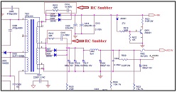
In my last article you have learned about the functions of the electrolytic and non-polarity capacitor (connected parallel) in the DC output line of a switch mode power supply (SMPS). In today’s article I will show you another circuit that has two components (resistor in series with a non- polarity capacitor) that are connected parallel with the secondary output diode of SMPS. Let’s take a look at the schematic diagram below. You can right click on the photo and choose “Open image image in Tab” to see the enlarged photo.

Figure 1
What is the name of such circuit?
It is called as snubber circuit but this circuit is generally called as RC snubber because it contains only a resistor and a capacitor. Snub means to brush off (or rebuff) and in electronics term it means to suppress.
Some snubber circuits like the one found in the primary section of SMPS is called as RCD snubber because it contains of a diode, a resistor and a capacitor (R1, C5 and D2) and the RC snubber circuit is C74 and R133. Take a look at the diagram below:
Figure 2
What is the function or purpose of Snubber circuit?
Snubbers circuits are placed across semiconductor devices for protection and to improve performance. It can do many things such as:
· Suppress over voltage (voltage spikes) and over current (current spikes) due to parasitic capacitances and parasitic inductances, by using resistors to convert the voltages into heat.
· Discarding the energy stored in the leakage inductance of the transformer.
· Reduce EMI by damping voltage and current ringing.
Why some SMPS designs does not have such circuit?
Take a look at the diagram below where certain output diodes (D529 and D511) does not have the RC snubber at all but to some designs (please refer to figure 1 ), all output diodes must have the RC snubber circuits. It may be some design engineers find the snubber circuits induce more losses (reduce circuit efficiency) than the losses they try to avoid.
Figure 3
What is the common problems in the RC snubber circuit?
It is actually quite rare to have problems in these two components. If the capacitor is open circuit or the value run, it may not have direct impact to the DC output but if it is shorted then the resistor may get hot and the power supply may go into shutdown mode or you can’t power up the power supply at all. If the vibrant colour of the resistor already changed to a darker colour due to heat, the best is to replace with the same type and value of resistor.
If the output diode is shorted then it is always good to check on these two components also. It is always a good procedure if you found a bad component, check also the corresponding components. It may be that corresponding components that have killed the output diode. Corresponding components can be any components that are located at the same DC output line of the shorted output diode such as the electrolytic and the non-polarity filter capacitors, inductors and etc.
Conclusion– By understanding each circuit functions in a circuit board, you will not be afraid of what you are actually looking at. Being said that, this mean the moment you hold the SMPS, your brain immediately will tell you that this is a RC snubber and you know the functions of such circuit and be able to test the components if they are faulty. This is why recognizing a circuit in a circuit board is so important and will eventually help you to speed up your troubleshooting work. Remember, to be a good repairer, you need to be able to understand many type of circuit functions in a circuit board and be able to recognize the components in those circuits. Well, that’s all for this week and you are welcome to comment related to this topic.
This article is brought to you by Jestine Yong. He is from Kuala Lumpur Malaysia and he loved electronics repair and blogging about electronics repair information. He is the author of the famous Basic Electronics Repair and SMPS Repair ebook . He is also a trainer and conduct electronics repair courses at Noahtech Electronics Training Center.
Please give a support by clicking on the social buttons below. Your feedback on the post is welcome. Please leave it in the comments.
P.S- If you enjoyed reading this article, click here to subscribe to my blog (free subscription). That way, you’ll never miss a post. You can also forward this website link to your friends and colleagues-thanks!
You may also interested in his previous repair article on the Functions Of Capacitors In SMPS DC output line
 (71)Dislikes
 (0)
(0)
33 Comments
Leave a Reply


Paris Azis
September 23, 2021 at 5:53 pm
Hello Jestine,
Very interesting and important information, well presented as well. This topic is important to be known to everyone involved in switching power supplies repairs. It is especially useful to all of those repairers of inverter welding mashies...Luck of this knowledge leads to repeated semiconductors replacement, frustration and disappointment on repairs...
Thanks for sharing it!
Jestine Yong
September 23, 2021 at 6:07 pm
Hi Paris,
You are welcome and glad that you liked it.
Tanks.
Jestine
Marinko
September 23, 2021 at 6:27 pm
Greeting,
Thank you for sharing such interesting information for home appliance service technicians.
A lot can be learned from you and other colleagues.
Marinko
Tehnician mechatronics
Jestine Yong
September 23, 2021 at 6:32 pm
Hi Marinko,
You are welcome.
Jestine
job espiloy
October 8, 2021 at 11:46 am
very informative and valuable technical info,
Thanks
Jestine Yong
October 8, 2021 at 2:10 pm
Hi Job,
You are welcome.
Jestine
Idelmar Ramon Mutte
September 23, 2021 at 7:40 pm
Gracias Jestine Muy interesante!!/
Thanks Jestine Very interesting !!
Jestine Yong
September 23, 2021 at 7:58 pm
Hi Idelmar,
You are welcome.
Jestine
Venugopal
September 25, 2021 at 7:07 am
Thanks for your great information.
Yogeshpanchal
September 23, 2021 at 7:42 pm
Sir, Thanks! for sharing info.
Jestine Yong
September 23, 2021 at 7:59 pm
Hi Yogesh,
Yo are welcome.
Jestine
Eric Rice
September 23, 2021 at 8:44 pm
Jestine,
Good article, but a question:
So in some ways it acts like a voltage current regulator, or better, a limiter without having a bleeder to ground?
Thanks,
Eric
Jestine Yong
September 23, 2021 at 9:36 pm
Hi Eric,
Still need a bleeder resistor to bleed off the charge in the filter cap once the power is turned off. And to improve voltage regulation by providing a minimum load resistance.
Jestine
George Nutzul
September 24, 2021 at 6:54 am
Thank you, Jestine for sharing this excellent article with us, and your knowledge. May God bless you and your family richly!
Jestine Yong
September 24, 2021 at 10:28 am
Hi George,
You are welcome.
Jestine
Babu MS
September 23, 2021 at 9:32 pm
very very useful information to attend smps problem.Thank you very much for sharing and I am requesting you to give many more articles please.
Jestine Yong
September 23, 2021 at 9:34 pm
Hi Babu,
You are welcome.
Jestine
Waleed Rishmawi
September 24, 2021 at 12:00 am
I did not know these circuits had a name. Thanks for sharing and as always very useful information added to my knowledge. Have a blessed day.
Jestine Yong
September 24, 2021 at 10:39 am
Hi Waleed,
You are welcome.
Jestine
Albert van Bemmelen
September 24, 2021 at 1:59 am
Thanks for another very interesting article Jestine.
Often diodes are also placed in non-smps power circuits antiparallel over the in- and output pins of three-legged voltage regulators, also to protect them.
From my time at Philips medical systems I was told that those regulators are not allowed in medical devices. Do not exactly know why, if that is true.
Jestine Yong
September 24, 2021 at 10:38 am
Hi Albert,
You are welcome. You are right about the function of that diode. I have not heard of why it would not be allowed to use it in medical devices. Possible that it does not have a feedback circuit as compare to LM2596 IC (4 Legs/pins IC)?
Jestine
Rodger Hopkins
September 24, 2021 at 3:21 am
Jestine,
Nice article.thanks for
sharing.
Jestine Yong
September 24, 2021 at 10:30 am
Hi Rodger,
You are welcome.
Jestine
Emile Jumala
September 24, 2021 at 5:56 am
Hi Sir Justine,
Thank you so much for sharing such informative and interesting article. I really love reading your articles, it give us additional knowledge.
Thank you so much! Keep safe...❤️
Jestine Yong
September 24, 2021 at 10:29 am
Hi Emile,
You are welcome.
Jestine
Parasuraman S
September 24, 2021 at 11:40 am
Vow, excellent insight into SMPS circuit. Very refreshing! Many thanks for sharing it, dear!
Jestine Yong
September 24, 2021 at 1:24 pm
Hi Parasuraman,
Thanks.
Jestine
Liviu FILIMON
September 24, 2021 at 3:17 pm
Hi Jestine,
Interesting article, an image on the oscilloscope of the signal taken after the circuit with the R C in series snubber and another image without improvement (one end of R or C lifted) were interesting to be seen the differences.
Regards.
Jestine Yong
September 24, 2021 at 9:32 pm
Hi Liviu,
Glad that you found the article interesting.
Jestine
Stephen
October 4, 2021 at 7:09 pm
Thank you .very new for me
Jestine Yong
October 5, 2021 at 10:17 am
Hi Stephen,
You are welcome.
Jestine
sukhdeo singh
October 13, 2021 at 11:25 pm
sir how we calculate the value of snubber network in smps circuit.kindly guide me.
Jestine Yong
October 14, 2021 at 3:48 pm
Hi Sukhdeo,
Since I'm not a SMPS designer, I'm not able to guide you on this.
Jestine