
How To Make Your Own HDMI Reader Easy
Only my RT809H universal Nand programmer can easily read the eeproms in monitors and television sets through HDMi or VGA connection but my other programmers didn’t have that option to read those ‘Biosses’. Why I decided to build such an adapter myself.
Also because the few ones that existed if still available were about 49 Euro each, and that seemed a very high price for such a simple device. Just soldering on those 19 tiny HDMi connector pins was no way to do that and I found a good and affordable HDMi adapter board that made creating this tool so much easier. But here first follows the circuit that helps to make all the right connections.

With this circuit reading those 24c02 Bios chips and similar eeproms in our devices is possible without even opening them by just connecting our HDMi cable to our universal programmer and our device. It is tested perfectly working on the TL866 and TL866II, and also on the GQ-4×4 universal programmers.
But no doubt will work on most other programmers too. Next photos show the parts that are needed to make this simple but useful adapter and the links to where they can be ordered.
We just select the right eeprom such as the 24c02 and in just seconds the data is read. Only when we use the GQ-4×4 programmer the chip is situated in the lower pins instead of the top of the socket, why we then need to extend the length of our original HDMi reader adapter so those pins can be inserted into that programmer too.
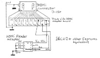
So HDMi pins 18 + 19 are connected to each other and to pin 8 to provide the Vcc to the chip we want to read. And chip pins 1 to 4 are HDMi ground , and chip pins 5 and 6 are HDMi pins 16 and 15. Keep in mind that you also need to switch on your TV or monitor before reading the chip else it will not work.
About the construction: With 2 of the above shown 2×4 2.54mm pin headers we simply plug-in our HDMi board into an epoxy 2x8cm protoboard with metallized through holes in which I first simply made the 4 connections with 0.2mm thin wire. And then soldered the pins of these female header connectors into. Next follows the result of the finished HDMi adapter reader. But first here also an example of that protoboard I only needed 4 cm in length from.
And the adapter reader was so made that it immediately was clear when the HDMi adapter board was inserted wrong because it then would stick out from the 4 cm long protoboard under it. Here the result.
Next photo shows how this adapter is inserted in the TL866 or the TL866II.
Next screenshots show the result of the read bios of my HDMi connected Samsung monitor.
And below the result when I used my new GQ-4×4 universal programmer.
Above photo showed the two extra 2×4 female header 2.54mm connectors I used to extend my HDMi adapter reader so it also would work in the previously shown GQ-4×4 programmer as the screen copy showed. But in the TL866 or similar programmers, the eeprom normally likely is positioned in top of the programmer test socket and then we won’t need to extend the 8 chip pins.
I hope that this article was an interesting read in providing all info for making this HDMi Reader tool for your electronics bench too!
Warning!: Do not try to write to your Bios without the right data in your programmer buffer first, as it most likely will kill the original data in your Bios of your monitor or TV. I know it is possible to delete the original data in your device and afterwards it no longer starts-up, and in such events we are still able to restore the device by using the RT809H Nand programmer. But I’ve not tested that with this DIY HDMi reader adapter!
Albert van Bemmelen, Weert, The Netherlands
Please give a support by clicking on the social buttons below. Your feedback on the post is welcome. Please leave it in the comments.
P.S- If you enjoyed reading this, click here to subscribe to my blog (free subscription). That way, you’ll never miss a post. You can also forward this website link to your friends and colleagues-thanks!
Note: You can read his previous article on Samsung G3 Series 3.5 Inch USB-Sata Adapter Repair
 (51)Dislikes
 (0)
(0)
21 Comments
Leave a Reply


Anwar Y Shiekh
June 4, 2021 at 9:04 am
Most impressive
Albert van Bemmelen
June 4, 2021 at 12:41 pm
Glad you liked the article Anwar! Keep in mind that still not all devices, monitors or TVs can be read this way. Like some modern 50 inch LG TVs (one that my brother bought). But most of them can be read over HDMi or VGA connection! Which enables you to make safety backups of those devices allowing you to save the very important eeprom data in case they get corrupted and they need to be restored to fix any boot-up problem. And getting that 'bios' eeprom data from manufacturer or other source afterwards is almost impossible why this HDMi reader is a good reason to make and use!
Albert van Bemmelen
June 6, 2021 at 9:09 pm
Addendum!: It must even be possible to readout the 'Bios'chips on LCD screens by connecting the HDMi reader 8 DIP socket to the 30 pins or 40 pins LVDS connectors as here follows, making it also a so called EDID reader! (which stands for Extended Display Identification Data)! But keep in mind to only provide the right maximum LCD LVDS voltage being 3.3V or 5V depending on the screen used. Which is easy when the voltage is set first on the universal programmer before reading the chip data. Again only 4 pins are needed. GND=pin 1 on the 30 pin LVDS, pin 10 on the 40 pin LVDS connector and pin 4 of our DIP 8 socket. VEEDID = pin 4 on both LVDS connectors and also pin 8 of our DIP 8 socket. EDID CLK = pin 6 on both the LVDS connectors and also on our DIP 8 socket. And last but not least EDID DATA = pin 7 on both LVDS connectors and pin 5 on our DIP 8 socket in our programmer. Data measured from an original existing EDID copy cable that worked exellent on my RT809H!
Albert van Bemmelen
June 7, 2021 at 12:24 am
PS: on my original EDID Reader pin 7 of the DIP 8 socket was also grounded with pin 4 but I guess there is no need to include pin 7 since it already worked on our HDMi Reader where it wasn't connected either. Pin 7 is the Write Protect pin of a 24c02 eeprom. And according to the datasheet it must be connected to Vcc or to Vss (gnd). Better not ground this pin because it will allow to overwrite the existing data. And when pin 7 is high it is Write Protected. But only the upper half of its memory 80h-FFh. But it also depends on the chip that was used in the LCD panel. Reading however normally never should cause any risk to the present data of our LCD chip memory.
Parasuraman S
June 4, 2021 at 9:20 am
My electronic appetite is not designed for imbibing and digesting these hi-tech professional skills! So, I read through and allowed it to fly off my frontal lobe! (LOL)
Albert van Bemmelen
June 4, 2021 at 12:25 pm
Just in case your appetite for a good and easy to build hi-tech tool tingles you to make one too Parasuraman, Know that I now am almost sure that this tool is also able to restore the defect eeprom bios chip data in monitor or TV like the RT809H can! Which I found out by accident when I by mistake pressed the wrong screen button that completely erased the chip in my Samsung monitor. But luckily I already had read the previously correct chip data into the programmer data buffer on my computer and was able to restore the chip by a simple write command afterwards.
Parasuraman S
June 4, 2021 at 6:22 pm
Yes, you are correct! Let me try! Many thanks for your comments!
Marinko
June 4, 2021 at 1:00 pm
sir, thank you for the information.
Very nice work.
I have the same kind of programmer for eeprome and I will make such an adapter for it.
greetings from Croatia
Albert van Bemmelen
June 4, 2021 at 4:56 pm
I'm sure with the given instructions making one won't be any problem Marinko. Hereby my greetings from The Netherlands too!
Albert van Bemmelen
June 4, 2021 at 1:45 pm
PS: Here the internet links to the items needed to make this HDMi Bios reader.
2 x 4 connector
HDMi Board
Epoxy protoboard 8 x 2 cm
Parasuraman S
June 4, 2021 at 6:23 pm
Clap! Clap! Clap!
Marinko
June 5, 2021 at 1:30 am
Thank you
dicksy
June 5, 2021 at 12:55 am
very important article.thanks a lot.im using rt809f programmer,but i cant program nand from that.because no hdmi connection in rt809 programmer.is it able to use your tool with my programmer.
Albert van Bemmelen
June 5, 2021 at 1:56 pm
Yes of course by selecting a 24c0X eeprom it must work on your programmer too dicksy! I haven't got a rt809F programmer myself, so haven't tested this but I'm sure you can read and likely write to the HDMi ports this way too! As long as there is a 2 wire communicating eeprom in your device that answers.
dicksy
June 6, 2021 at 1:45 am
thank you very much mr albert.these days we are quarantined because of pandemic.all the shops are closed.after this i will make your tool and let you know the result.thanks again
Albert van Bemmelen
June 6, 2021 at 12:36 pm
Understood dicksy. But can't you also just order online from Aliexpress on the links I gave in above comment? Or do you mean that now also the post offices are closed in your country too, and no one delivers at your doorstep because of the pandemic now? The electronic shop in my town doesn't have any of the items so I always need to order online. And then just wait several weeks for the items to arrive.
Waleed Rishmawi
June 5, 2021 at 1:48 pm
very informative article. thanks for sharing. I do not deal a lot with programming but this devices seems very interesting to have and use. have a blessed day.
Paris Azis
June 5, 2021 at 3:09 pm
Albert,this is an excellent -first class- article, most useful to everyone involved in electronics' repairs. A simple/typical "thank you" is definitely not enough to outweigh this endeavour of yours. Its value is leveled much higher than that...
Yogesh Panchal
June 6, 2021 at 11:56 pm
Albert,
Thanks! for informative article.
Gregory Brettell
June 8, 2021 at 2:01 am
Very good post ... thank you!
Andrea Del Corso
June 21, 2021 at 10:11 pm
Ottimo lavoro,come al solito!Grazie Albert.
=====================================
Great job, as usual! Thanks Albert.