
Making A Working Jim Williams Based Pulse Generator
Recently I started making one of those famous Jim Williams based avalanche fast rise pulse generators. I therefore bought a set that consisted out of 3 OSH PARK pulse generator boards.

And all info including the part list was given on the OSH PARK website on https://oshpark.com/shared_projects/KrhgN8JM . Previous OSH Park schematic version 2.4 was old version from februari 2017 that still used a 1…27pF 100V max capacity trimmer. And was replaced into a 5…27pF 100V Murata capacity in the last following march 2017 version also still v2.4 board. And it was designed to work with the now no longer available 2N2369 transistors that were good avalanching transistors that generated fast rising pulses on the about 90V DC that the LT1073 SOP8 circuit provides. And in march 2017 version 2.4 was the tolerance of R3 and R7 (10M and 24K) apparently changed into a 1% version. Newer transistors apparently are ‘better’ protected against avalanching on the collector to emitter from low voltages and now withstand higher voltages to protect them from any destructive damage which we do not need here. As we limit that current.
With such a special fast pulse generator based on Jim Williams design we are able to determine the bandwidth of nearly any oscilloscope by measuring the time the pulse needs to rise according to the formula 0.35/pulse time T = bandwidth. Or by measuring that 1/T frequency x 0.35 = bandwidth scope. If for instance the scope bandwidth is 350 MHz as it on my 2465A oscilloscope is we should measure about 1/1GHz pulse rise time (measuring on the rising edge between the start time at 10% and end time at 90% time of the pulse). Because 0.35 times 1Ghz gives a bandwidth of exact 350MHz!
Above the first and most difficult part in making the OSH Park pulser, adding the tiny 5 pin microUSB connector. The rest is much easier. Below the finished generator top side. (After my modifications!).
The OSH Park board in its given march 2017 circuit version didn’t make any of my 2N2369A transistors oscillate in fast avalanche mode. At all! It only showed an about 2 Hz random pulse.
I checked this by placing all my 2N2369A transistors in another fast rise pulser circuit from Kerry Wong. Which can be found at http://www.kerrywong.com/2013/05/18/avalanche-pulse-generator-build-using-2n3904/ . Which are both boards on the left and in the middle in below photo.
And I used my DY294 again because it can provide an excellent high DC supply voltage to feed my transistor avalanching pulse generators under test.
And where Kerry used a 2N3904 transistor (that according to Kerry also needs a higher voltage of about 120V) I tested my 2N2369A types instead. They worked perfectly at about 122.5V DC on the 220Kohm resistor used in serie with the collector of the 2N2369A. And the collector resistor of 1Mohm, or even 10Mohm as was used in the OSH Park circuit and in a similar circuit never worked!
Since those better at lower voltages avalanching 2N2369 transistors no longer can be found I had to modify the OSH Park circuit so that the OSH Park boards now also work with the few but still presently available 2N2369A transistors that only avalanche on voltages of at least 123V and higher!
I tested several transistors by using Kerry Wong’s circuit to test on what voltage they started oscillating in avalanche mode. Like with testing the BSY10 transistor that apparently needed an even much higher collector voltage of about 175V DC that my DY294 perfectly was able to provide as next photos show.
Above shown circuit from Kerry I used to test my transistors with. The 2N3904 transistor he originally used in the above circuit in my test even needed about 163.7V on the 220K resistor before it avalanched in a good way as my DY294 did show on its display. I replaced the 22pF on my previously in the middle shown soldered Kerry board by the same Murata 100V 5…27pF capacitor as the OSH Park board used to continue my tests. Because this makes it possible to change the frequency and so the pulse shape and the generated amplitude. These test revealed that I also needed to increase the voltage that the sop8 LT1073 generator chip on the OSH Park boards provided by at least another 30V ! And from the 5 chips I received through Aliexpress one was already defect and a second one only gave 50V out max. Chips 3 and 4 were fine and chip 5 wasn’t used or tested. But the just 89V that they gave was way too low and the collector series resistor way too high!
Next photo shows an example of Kerry Wong’s nice oscillating pulse generator when a transistor avalanches in a good way and fast enough by creating very fast high rising pulses. Which never happened on the OSH Park boards at the just 89V they provided and the too high 1Mohm value!
I also checked the datasheet of the LT1073 and started testing the OSH Park board by changing resistor R1 from the originally 100 ohm value into 220 ohm. It made no measurable difference and only limits the current if generator problems occur! Doubling the capacity of C4 10uF made no
difference either, and especially increasing the collector resistance R2 from 1Mohm to 10Mohm as in another similar pulse generator circuit was used made no positive change at all! (that also still used the no longer available at a lower voltage avalanching 2N2369 type transistor). The about 90V from the OSH Park board when applied to supply the Kerry Wong circuit however did work! Which revealed that the 220Kohm collector resistance was a good substitute for the too high OSH park 1Mohm resistor.
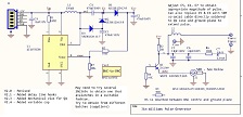
According to the LT1073 datasheet the present OSH Park voltage can be calculated from the formula: 212mV x (10Mohm/24Kohm +1) = 88.54533V DC. To get at least about 123V that the DY294 showed when powering the Kerry circuit with a 2N2369A transistor in it we find : 212mV x (13.9Mohm/24Kohm +1) = 123V. So we need to increase the 10Mohm FeedBack resistor (pin FB to our LT1073) by at least another 3.9Mohm which is exactly what I did by placing another resistor in serie with the originally used 10Mohm which at the same time is a safer replacement for the higher output voltage that is generated on the OSH Park board. Next photo shows the result of one of the on my 2465A oscilloscope tested OSH Park boards when the time base was set into the highest possible trigger frequency and also the X10 Mag(nitude) zoom function was selected.
And we’ll notice that at that point no further zooming in at the very fast rising pulse is possible! Hence why it makes possible to now also determine our scope’s bandwidth with this fast rising edge pulse. Notice in the taken scope’s front photo that we use channel one’s 50 Ohm yellow input selection (since our OSH Park output transistor emitter impedance is also 50 ohm which prevents signal reflections), and also notice the yellow X10 MAG push button selected in the top middle.
With the position knob left of the X10MAG push button we can find the exact position of our zoomed in on fast rising edge pulse.
Previously photo showed that our OSH Park board oscillated on a fast 560KHz by producing very fast like vertical ‘needles’ looking pulses. And on the photo below we can see how our fast rising pulse (our previous ‘needle’) looks like when we again turn the SEC/DIV into the highest measurable and triggerable frequency possible but now without using the X10MAG push button.
The higher the set oscillating frequency is set, the lower the amplitude is and vice versa. (adjustable with the 5…27pF 100Volt max Murata trimmer, that apparently no longer are produced).
On last photos my 3 now perfectly working Jim Williams OSH Park Fast Rise Pulse Generators are shown at their Murata 5…27pF adjustable trimmer sides.
Although I ordered the SMT_Inductor as was given in the OSH Park BOM list from Digikey (which I had to order from their daughter firm SinusS, since I’m not an ordering shop owner) they were not the 150uH 3mm inductors size as was mentioned. But they were with measurements 7x7x5mm a bit higher (151KU590mA MSCD75-151). But the 151uH smt-inductors ordered through Aliexpress were unexpectedly exactly the given 7x7x3 mm size. (But I however only used the 5 mm higher ones here).
Of course we also must only use 50 ohm coax cable (RG58 and similar) to connect our device to our scope input channel with!
Conclusion: After changing R2 from 1Mohm into a 224 resistor (220Kohm! I also used a larger 1206), and changing the 10Mohm 1% resistor into a 13.9 Mohm resistor ( by adding a serie 3.9Mohm also 1% resistor) my OSH Park boards all finally worked perfectly! I also used the same better performing ST 2N2369A transistors that all had a brownish looking substance that was used to seal the semiconductor and its legs into the metal cap it was housed in. And for the 50 ohm emitter output resistor I just used two 100 ohm resistors soldered in parallel onto each other. So if you also want to test the bandwidth and the limits of your oscilloscope these circuits are a good and affordable way to do that! And this by Jim Williams designed avalanche pulse tester works on almost all oscilloscopes without much effort!
Warning!: Because now the output voltage on the last capacitor being C2 is higher than the previous generated voltage was, I also replaced only C2 by special ordered 250V 470nF capacitor. The originally max 100V value capacitors C1 and C3 can be left unchanged because those voltages are still at max around 63V. (But only when a good active transistor is acting as load on the 220Kohm collector resistor, else the values are dangerously high for the 100V max C1 and C3 caps).
Albert van Bemmelen, Weert, The Netherlands.
Please give a support by clicking on the social buttons below. Your feedback on the post is welcome. Please leave it in the comments.
P.S- If you enjoyed reading this, click here to subscribe to my blog (free subscription). That way, you’ll never miss a post. You can also forward this website link to your friends and colleagues-thanks!
Note: You can read his previous article on Tektronix 2465A Repair
 (37)Dislikes
 (2)
(2)
8 Comments
Leave a Reply


Parasuraman S
June 18, 2021 at 12:47 pm
Very informative article in building electronic devices, in this case, the most essential Pulse Oximeter during this Pandemic period. Well done and many thanks for sharing!
Waleed Rishmawi
June 18, 2021 at 5:27 pm
very deep informative article, nice explanation and detailed photos. I thank you for sharing it, I am sure it took you a while to make and write the article. have a blessed day
Albert van Bemmelen
June 19, 2021 at 6:37 am
Nice thing to know is that Kerry Wong's Jim Williams avalanche pulser circuit didn't use a LT1073 with special HV fast recovery rectifier diodes to generate the needed high voltage that enables the fast recovery HF transistors to avalanche. Like the special MURS120 diodes used in the OSH Park circuit. He instead just used several very cheap 1N4148 diodes to generate the HV +120V output which is quite remarkable!
ALBERTO GRACIANO LAPA
June 20, 2021 at 5:13 am
Excellent
William Shaw
June 30, 2021 at 5:32 am
A step up in the theory department! Very much appreciated. Not absorbed immediately by the less than experienced on first reading but very helpful in extending our knowledge base.
Thank you!
Albert van Bemmelen
September 11, 2021 at 3:48 pm
PS: I also designed a perfectly matching 3D printable case to place these OSH Park Generator boards safely in. By changing and testing another found design until it was right so it exactly fitted the measurements of the boards with the connectors on it.
Albert van Bemmelen
September 13, 2021 at 2:01 pm
PS2: There is a real practical reason behind this article why I build this Jim Avalanche Fast Pulse Generator! I need it to calibrate my Tektronix 2440 350MHz Memory oscilloscope in one of the calibration step procedures. Without it my Tek 2440 never will work correctly on the external calibration that also needs to be executed after the internal - automatic - calibration was done.
Albert van Bemmelen
October 19, 2021 at 5:18 pm
Update 12 october 2021: the final CTE external calibration step recently was not done by using the in this article made Jim Williams Fast Rise Pulser. Instead I used my about <50 (?) years old second hand bought Systron Donner 100A Pulse Giver to pass this final Tektronix 2440 scope test! Which also can be read in the posts after Part4 of my 2440 scope repair. The needed about 100KHz square wave calibration pulse is not critical. And afterwards my Jim Wiliams pulse giver tested my scope's bandwidth giving the about 300 MHz that was expected.