
No Schematic? Don’t Worry, Here Is A Way To Solve – PHOENIX Open Care Warmer OCW100
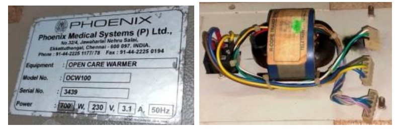
The power supply board of this warmer which also handles the heating of a carbon crystal element, was brought to me with the complaint that the connector portion of the heater burned due to power hike and that portion was found charred. What you see in the second picture above is its AC step down Transformer. Let us have a look of this board:
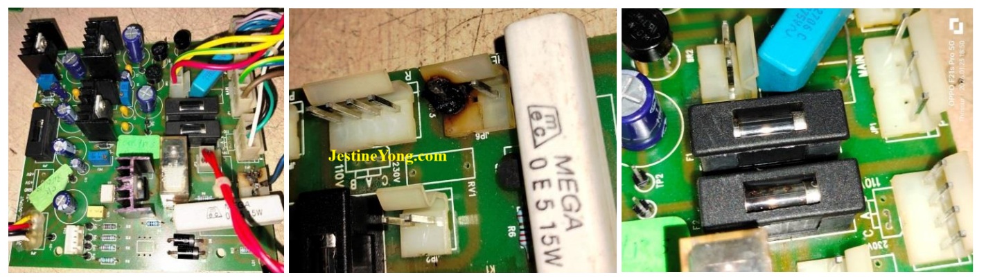
First duty was cleaning the board and removing the burnt out components. Three fuses were found burnt. I also noticed that the BTA12 Triac, which handles the heater load, was also short. But the heating element was found ok on testing with Analogue multimeter. The board was combed for any more defective components and all defectives were replaced. When I applied the power, the DC outputs of 5V & 8V were steady. In order to study how this circuit works, I tried my best to obtain a circuit diagram. But as these are custom made protected circuits, nothing could be done in this line.
I fetched the mother board, transducer and other connectors in order to connect and check. I found that the switching through the Triac was taking place, but it did not remain steady. Since using a heating element keeping it open on the service table was a risky factor and further because of the brittle nature of the carbon crystal element, I used 200W bulb as a load. The opto-couplers used in the circuit were of special types with darlington transistors inside.
The numbers were: 4N33 & MOC3011, which were General Purpose 6-Pin Photodarlington Optocoupler & 6-PIN DIP Zero-Cross Optoisolators Triac Driver Output. Let us have a look at its uses along with the Relay and Triac:
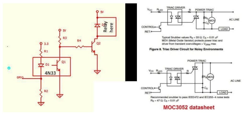
Though the IC number of MOC is different, the functions are same. Such opto-couplers are used in these types of devices which require precise current adjustment, as these are baby warmers. Following are the pictures of the controller board and details of ICs used in the board:
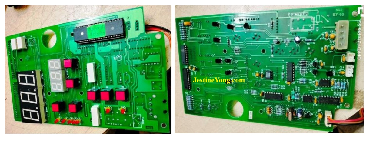
ATMEGA 8535 – 8-bit Microcontroller with 8K Bytes In-System Programmable Flash ULN2803 – Octal High Voltage, High Current Darlington Transistor Arrays SN74HC245 – Octal Bus Transceivers With 3-State Outputs CD74HC138 – High-Speed CMOS Logic 3- to 8-Line Decoder/Demultiplexer Inverting and Noninverting DS1232 – Micro Monitor Chip – Halts and restarts an out-of-control microprocessor. Holds microprocessor in check during power transients. Automatically restarts microprocessor after power failure.
HD74HC74 – Dual D-type Flip-Flops (with Preset and Clear)
HCF4051B – SINGLE 8-CHANNELANALOG MULTIPLEXER/DEMULTIPLEXER
OP07C, OP07D, OP07Y PRECISION OPERATIONAL AMPLIFIERS
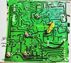
The four wires that come to the PS board were Ground, relay on command and gate control for MOC3011. Control of the driver circuit is to ensure that the heating is done as per selected setting. In order to study the function of the PS board, I took a picture of the bottom side of the PCB, took a print out and marked the components on the paper. Let us have a look at the schematic obtained; which of-course was a result of minute study and markings done and after repeated attempts. First I used pencil, checked and rechecked markings, carried out corrections before overwriting with a black sketch pen.
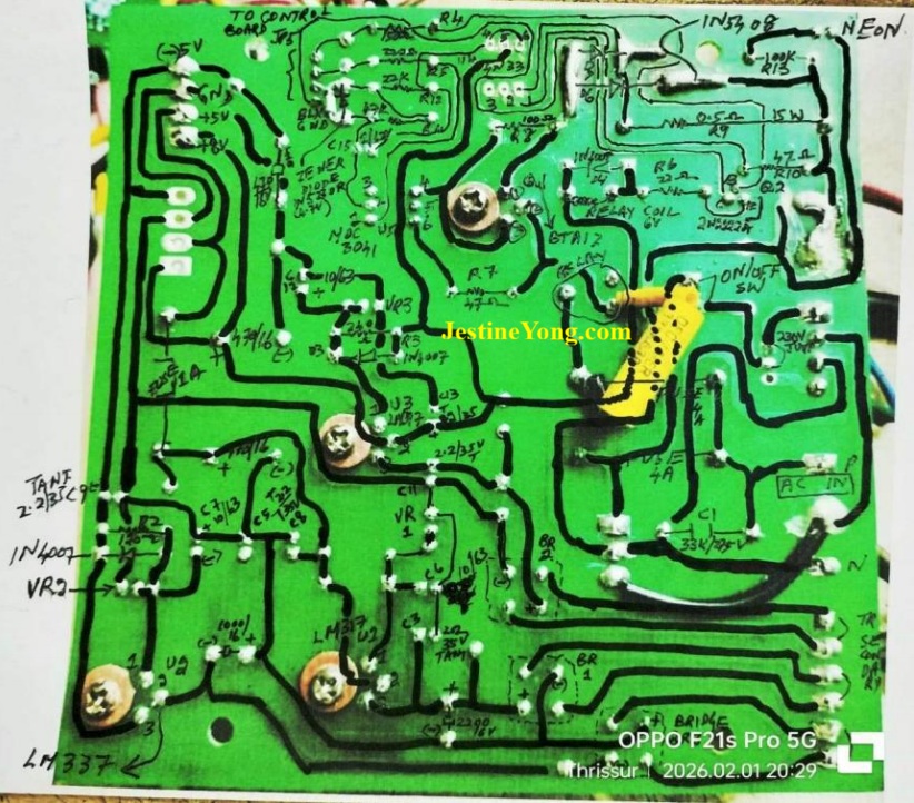
It was possible only because it was a double sided through-hole PCB. Anyhow, this helped me understand the function very well. The triac passes on 230V AC to the element upon getting triggered. The 3011 is switched on by the uController, upon which the relay gets on to connect to the heating element. The current sensing is done by the 4N33 which works as a pulse generator to boost the voltage for the element to glow. The pulse for triggering this, is from the uController. Having understood this much and after checking that 8V and 5V were present, I connected the board to the uController and applied power. I saw the bulb glowing, but it went off after a few seconds. On checking that after switching on, the pulse required for boosting the voltage was not coming out from the uController. So, in all probability, that port has gone bad. The track upto the pin was found ok and it was not strained or cut.
That means either the IC is defective or the software has got corrupted. I fetched the ATMEGA IC and also bought an ATMEGA programmer but the interfacing software was an issue and I could not do much progress on it, mainly because of other pressing work. So, I stopped further work on the board and sent the entire kit to a firm which handled manufacturing of medical equipment, as they had all the facilities to copy the software, if it was not protected or write a fresh program for its proper function. But as far as I am concerned, my job was over and here is the proof of the damaged board working:
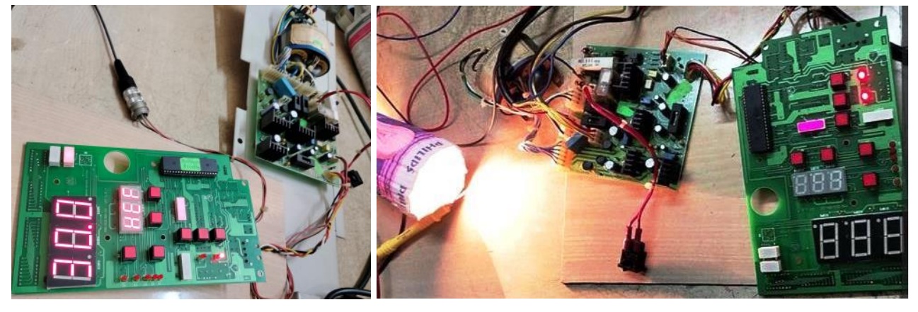
So, a contended satisfaction got collected to the bag!

This article was prepared for you by Parasuraman Subramanian from India. He is 76 years old and has more than 30 years’ experience in handling antique equipment like Valve Radio, Amps, Reel Tape Recorders and currently studying latest tech-classes conducted by Kerala State Electronics Technicians’ Association. He has done graduation in BBA degree, private diploma in Radio Engineering and retired as MD of a USA company. Presently working as Consultant to Hospital and other institutions.
Please give a support by clicking on the social buttons below. Your feedback on the post is welcome. Please leave it in the comments.
P.S-If you enjoyed reading this, click here to subscribe to my blog (free subscription). That way, you’ll never miss a post. You can also forward this website link to your friends and colleagues-thanks!
You may check on his previous article on Relay Rattling Problem Solved In AMREX UPS Model PROVIEW-600
 (33)Dislikes
 (0)
(0)
14 Comments
Leave a Reply





Albert van Bemmelen
August 22, 2026 at 6:00 pm
With each article you use new techniques and also add new tools that makes reading about these repairs more exciting!
About reading and flashing these ATmega AVR chip originally developed by Atmel and now produced by Microchip Technolog, I know that these can be programmed in-circuit serial, but also in a so called parallel programmer out-circuit in parallel mode (databus d0-to-d7 wise). But only if the configuration fuses used while the firmware was flashed into them had no protection bit set to prohibit them from being able to read out their content. Which apparently also with special tricks sometimes depending on the type AVR used can be undone.
But when for instance the serial programming mode no longer works because the AVR controller is somehow blocked or corrupted, then only the parallel programming mode can override or unblock this issue.
After adding the special serial and parallel RT809H programmer and many other mostly parallel programmers I recently added the cheap but interesting CH431 and CH431 v1.7 eprom mini programmers to my digital arsenal. v1.7 adds the option to be able to select Vcc from 1.8V to 2.5V or to 3.3V and also to 5V. The older CH431 mini programmer has a hardware bug that may destroy your bios chips unintendidly because it always outputs 5V on all SCL and SDA datalines!, even when Vcc was safely set to 3.3V! But this can easily and safely be fixed as many youtube videos show. Which in short involves powering the used CH431 pin28 Vcc pin from its 3.3V regulator output instead of using the 5V from the USB port it is originally connected to.
Parasuraman S
August 22, 2026 at 8:35 pm
I read through your inputs and finished it just for the sake of saying that I read it. Honestly, most of that went above my head! Nevertheless, I have copied the text and saved it in Electronics Folder for reference as and when I get a chance to do further research on it. Many thanks for your expert comments and suggestions, dear Albert!
Albert van Bemmelen
August 22, 2026 at 11:28 pm
As you know most of the TV repairs are above my experience level dear Parasuraman. I only shared the mentioned digital information on programmers and AVR processors because of your smart move in buying such an ATMEGA programmer. Sadly you didn't share any information about what interface program you used. AVRDUDESS is a GUI for AVRDUDE that works in Windows and is a good tool for programming Atmel microcontrollers. I guess your ATMega programmer was a cheaper 5 or 6 pin ISP or ICSP serial mode programmer? With those you are stuck if serial mode communication in the ATmega is blocked or the protection bit was set. You can reset all fuses in parallel programming mode re-use these processors but then also lose the program data in the ATMega chip. So I wonder if that firm will be able to read out or restore the pre-programmed firmware in that case when it is copy protected.
Parasuraman S
August 23, 2026 at 2:28 pm
Since another complex work is on my table and I have to focus on that, right now I have no answer to your questions. The number printed on the programmer is USBASP V2.0 and the IC used has a name ATMEGABA AU 1423. On the cover there is a printed number : 6645-09 AVR Programmer for ATMEL Processors. Only this much I can provide for the time being. Many thanks for the time you are spending to help me out.
Albert van Bemmelen
August 23, 2026 at 3:40 pm
Interesting read here how to program AVR chips with the CH341 mini programmer: https://ericdraken.com/avr-amtel-attiny-ch341a-isp-programmer/
There even is a CH341 to AVRdude patched version support (fullspeed and bitbang) for Windows WCH official driver and Linux (based on Alexey Sadkov patch and WinChipHead sources) here: https://github.com/maxxproff/avrdude-ch341
or this one here: https://github.com/Trel725/chavrprog
PS: on page 237 of the ATMEGA8535 datasheet it mentions this => The ATmega8535 provides six Lock bits which can be left unprogrammed (“1”) or can be programmed (“0”) to obtain the additional features listed in Table 97. The Lock bits can only be erased to “1” with the Chip Erase command.
Albert van Bemmelen
August 23, 2026 at 4:40 pm
Additional info: Reading bios or processor chips IN-CIRCUIT often fails simply because the Vcc that comes from your 6 or 10 pin ISP cable and goes to the attached board also drives all other parts simultaneous in your attached circuit. Which may cause databus conflicts or erratic behavior that blocks reading out your data correctly, which shows when you Verify the data in your computer buffer to the data still present in your bios chip or processor chip, when it fails to confirm they are identical!
This In-circuit problem when for instance using a mini programmer like the CH341 with its 8 pin wire clip easily is avoided by cutting the Vcc pin 8 wire on the clip. And then simply feed the board with the intended chip to read-out or program with its original power supply. This then always fixes the Verify failing issue and your read data is okay!
Parasuraman S
August 23, 2026 at 6:36 pm
Many thanks, I have saved this also and shall try as and when I get back to it.
Parasuraman S
August 23, 2026 at 6:35 pm
Many thanks, I have saved this also and shall try as and when I get back to it.
Albert van Bemmelen
August 29, 2026 at 7:49 am
Addendum: When Bios eeprom chips are in-circuit grounded to GND on for instance the Write protect pin, any attempt to read and copy the Bios in-circuit will fail. No matter if the Vcc pin 8 wire on our test clip was cut and that board with Bios chip on it was power fed externally or not. Today that happened when I was trying to read and copy the 25VQ32 Bios in my Cabletech DVB-T2 receiver. It could never be read at all in-circuit with As-Programmer or Neo-Programmer and my CH341 Mini Programmer and had to be removed from its board before it finally could successfully be read and copied!
Yogesh Panchal
August 22, 2026 at 8:00 pm
Good Fix! Sir
It has become a habit of mine to note down details—such as wiring diagrams and part numbers or codes—of small appliances brought in for repair, as these can prove useful for future jobs.
As Medical devices are very precision it was your right decision to contact manufacturer.
Regarding Albert's opinion on programmers—I also own a CH341A programmer, but every programmer has its limitations. Given the constant evolution of technology, it isn't feasible to own every type of programmer—especially when you don't handle that specific kind of work regularly. It is better to simply get the job done by someone who already has the right equipment.
Parasuraman S
August 22, 2026 at 8:37 pm
I am with you in the boat, dear Yogesh Panchal! Many thanks for your comments!
Mark J
August 23, 2026 at 2:14 am
Good job once again Parasuraman. Very informative article. Thank you for sharing.
Parasuraman S
August 23, 2026 at 2:29 pm
Many thanks, dear Mark!
George Kiama
August 29, 2026 at 1:24 am
What is an octocoupler and what is it's function