
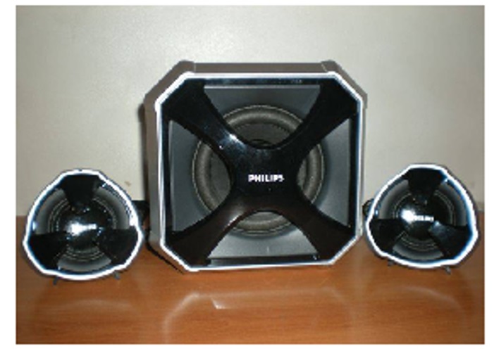
Philips MMS 430 Volume Control Unit Modification Wiring Details
Received Back this speaker system almost after 10 years. Found volume control PCB is Broken again.
But this time I decided to keep volume control & ON/OFF switch out of the box, instead of fitting it inside the satellite speaker.
https://jestineyong.com/philips-mms-430-speaker-universal-board/
Refer to my article above, in comments many people asked about volume control switch and on/off switch details but at that time I had already returned the unit so I couldn’t help but after so many years I got the chance to share the details again.
Since many years we techie friends looking for the circuit diagram so that we can modify volume control & On/Off switch but we could not find any.
This is original Volume control PCB.

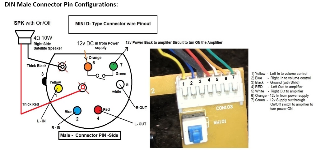
Trace side PCB Layout with Marking of CON103 wire color so that we can come to know which wire is connected for what purpose.

I traced the circuit and put marking on it.
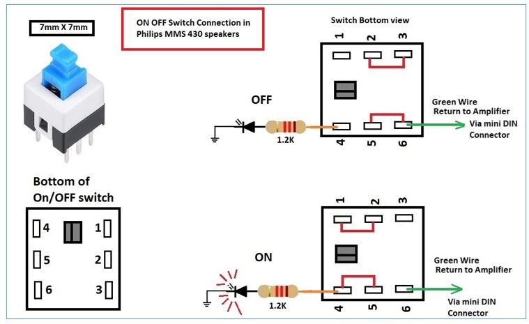
Not sure about On/Off switch because it’s pins are shorted exactly opposite pins. So I have to check another Circuit in Woofer Box also to figure out exact working of the connection.
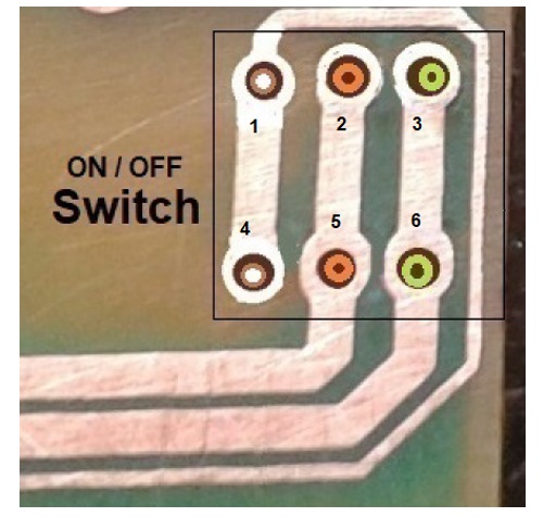
As power coming from the Woofer BOX through mini DIN Connector, so we have to find out which wire give us 12v. which is going to Middle (Common) Pins of the On/Off switch.
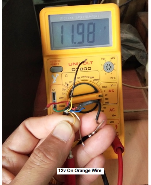
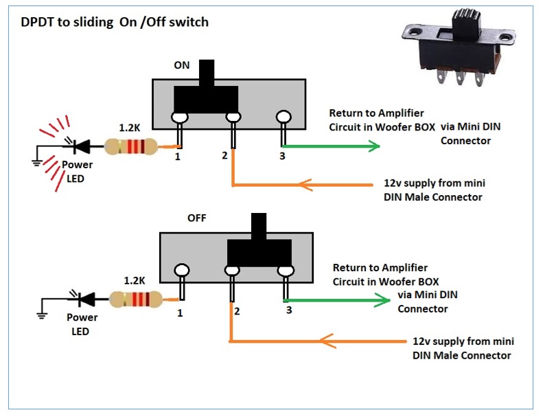
For confirming I checked voltages on all wires, 12v coming on Orange wire. (Power Input from DIN Connector). On /Off switch Pin 1& 4 is going to LED Indicator through 1.2K Resistor, Green Wire traced, it is going Back to the Amplifier in Woofer box via mini DIN connector to Logic ON / OFF circuit.
Volume Control Pinout
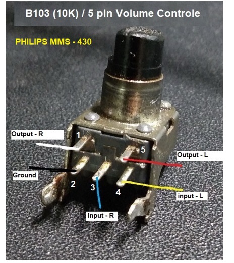
These are over all idea how parts are connected.
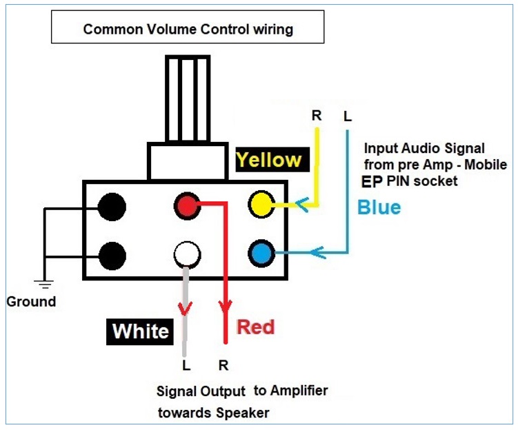
If you want to Replace Volume Control to normal 6 Pin Potentiometer wiring should be like this.
FOR TACTILE PUSH BUTTON SELF-LOCKING ON/OFF SWITCH CONNECTON.
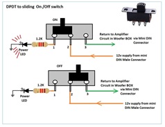
& IF YOU WANT TO USE SLIDING SWITCH:
This way we can put External Volume control with On/Off switch & Power Indicator LED in this unit.
I have done wiring for Speaker Volume Circuit & it is ready to install but still waiting to get proper fitting so that I can keep this circuit out of the box. sharing the final unit work very soon.
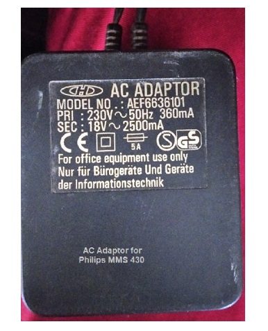
Original Power Adaptor Rating:

This article was prepared for you by Yogesh Panchal who works as a Computer Hardware Engineer in Mumbai India.
P.S- Do you know of any your friends who would benefit from this content that you are reading now? If so, forward this website to your friends or you can invite your friends to subscribe to my newsletter for free in this Link.
Note: You can check his previous repair articles on Mini Tactile ON/OFF Switch Confusion
 (39)Dislikes
 (0)
(0)
11 Comments
Leave a Reply


Albert van Bemmelen
March 8, 2025 at 7:01 pm
I understand that this is another repair that also mentions the problems you had in the previous article with using the wrong type of tactile pushbutton switches.
The only Philips devices I still have at home are an old 'cheaply plastic designed' analoge laserdisc player of untrustworthy quality! (unlike my super quality very well manufactured Pioneer Laserdisc player CLD-S315), and a couple of older Philips shavers. Plus a second hand in the past repaired Philips CD-I player. And a lot of those Philips 'golden' laserdiscs I had of the 80's all were only fit to throw in the garbage. Because they no longer were playable because of the terrible manufacturing process that Philips had used! (the two 'golden' laserdisc sides were so extremely badly glued to each other that immediately caused the metal layers to rot and turning into black useless plates - unlike the 'silver' Pioneer Laserdiscs that even after 40 years are still in excellent condition!).
YOGESH PANCHAL
March 9, 2025 at 3:48 pm
Albert,
In fact, I have come across recently, some repairs are misguided due to these types of switches. I found in this product that despite the poor PCB placement design, the products are of very rugged quality.
Parasuraman S
March 8, 2025 at 8:36 pm
That's a lot of investigative and innovative work done! Many thanks for sharing very valuable info about controls and switches. I am going to save this for reference! Good job there, Yogesh Bai! Well done!
I eagerly look forward to receiving your updates!
YOGESH PANCHAL
March 9, 2025 at 3:49 pm
Sir, Thanks! for your kind words.
Mark J
March 9, 2025 at 4:32 am
Yogesh good article very informative. Thank you for sharing.
YOGESH PANCHAL
March 9, 2025 at 3:50 pm
Thanks!Mark J
Imoudu
March 10, 2025 at 4:04 am
Thanks sir for this invaluable information,its worth to be saved for reference.
YOGESH PANCHAL
March 10, 2025 at 2:44 pm
your Welcome!Imoudu
Tyrone Arendse
March 13, 2025 at 4:40 pm
Thank you for sharing
YOGESH PANCHAL
March 13, 2025 at 10:53 pm
Your welcome!Tyrone Arendse
Ulises Aguilar
July 27, 2025 at 7:03 am
good after noon sir very ingenious