
Should You Test Resistors OnBoard Or OffBoard?
I often got technical questions from my training students and one of the most common questions was about whether to test or check resistors onboard or offboard. My answer to them was it depends. For your information, resistors in any circuit board are often connected in parallel to some other parts. It can be connected parallel to another resistor, capacitor, diode and etc. Resistors also can be connected in series with another component. Let’s take a look what are the implications of testing resistors Onboard and Off board.
Onboard resistor testing
Onboard resistor testing means you test a resistor using your digital multimeter (DMM) while the resistor is still soldered onto the circuit board.
Pro:
- It saves time-meaning to say that you do not need to remove one of the resistor leads in order to test the resistor value. If the resistor value is 10k and onboard testing is showing 10K, you know that the resistor under test is good.
Cons:
- If there are resistors connected in parallel, the value that you measure will be lowered than the resistance of the resistor itself.
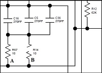
- If a resistor is in parallel with an open resistor of the same type and value, the resistance measured across the remaining good resistor will still be read on the Ohmmeter. This can be misleading. Let’s take a look at the diagram below:

As you know that when two similar resistors value are connected in parallel the total resistance would be half of the resistor value. For example, if a 10 Ohm resistor value is connected parallel with another 10 Ohm resistor, the Ohms reading that you will get when you measure either one of the 10 Ohm resistor would be 5 Ohm.
Now, assuming you are testing on the A and B resistor in the above diagram, and you did not check if both resistors are connected parallel or not, if you placed your test probes on resistor A you will get 10 Ohm which is fine. Then you moved your test probes to test B resistor, guess what value you will get? You will get value of 10 Ohm! Why? Because you are actually measuring resistor A if resistor B is open circuit. You may be thinking both resistors are good in which actually one of them is bad (resistor B). If you proceed to test on other components hoping to locate the fault in the equipment, I can say you will not be able to find out the fault because your mind already told you that both resistors that you have tested were good. You have been misled!
Now, I believe you can clearly see the disadvantage of testing same value of resistors onboard. Unless if you have confirmed that both resistors are not connected in parallel then it is okay to test the resistors onboard.
A typical example of same resistors value (4.7K ohm) connected in parallel
- If there is a capacitor that is connected parallel with a resistor and developed short circuit, when you test on the resistor, it will show very low Ohm!
Example, if capacitor C19 has developed a direct short and when you test resistor R1017 your DMM will show a very low ohm or even zero Ohm.
A typical example of an electrolytic capacitor connected parallel with a resistor.
- Many times a circuit can have few or many parallel paths thus testing a resistor in such situation will not give you an accurate resistance reading.
Offboard resistor testing:
Offboard resistor testing means you test a resistor using your digital multimeter (DMM) while one of the resistor leads is soldered out from the board.
Pro:
- It will provide you with a very precise resistance test result because you are checking only the resistor alone and not the sum of all other parallel path components. This means if a resistor have even a slight tolerance value out, you will be able to notice it.
Cons:
- It will consume much of your troubleshooting time if the circuit board have lots of resistors. You need to solder out all resistors leads in order to get an accurate reading value.
Note: If an experience repairer is able to locate to a small faulty section of a circuit board, he/she would be able to test all of the resistors. Since they are experience repairers, there is no doubt the way they pull out one of the resistor leads; to test it and solder it back would not be an issue to them because they have the speed to do the job.
So which method of testing resistor is the best?
If you would like to test resistors onboard always made sure there is no similar type and same resistor value beside the resistor that you are testing. This is to avoid the misleading test that I have mentioned above. If you get a too high or too low Ohm reading or a reading that made you uncertain to decide if it is a good or bad value, the best is to test the resistor offboard.
Normal through-hole resistor rarely short circuit or decrease in value, usually the problematic resistor value would either increase in Ohm or no value at all (open circuit). As for a problematic SMD resistor, the Ohm value can increase, decrease, short circuit and no value at all (open circuit), so take note on this.
Conclusion– It is always a preference choice of an individual whether to test a resistor Onboard or Offboard. Some experience repairers would choose to test the resistors while the power is applied. This way they can pinpoint a faulty resistor fast but one must truly understand how the circuit work and if there is a schematic diagram, it would be a plus point. Or you can use all the combinations testing methods above to test resistors. What is your resistor testing method? Please post a comment below that is related to this topic. Thanks!
This article is brought to you by Jestine Yong. He is from Kuala Lumpur Malaysia and he loved electronics repair and blogging about electronics repair information. He is the author of the famous Basic Electronics Repair and SMPS Repair ebook . He is also a trainer and conduct electronics repair courses at Noahtech Electronics Training Center.
Please give a support by clicking on the social buttons below. Your feedback on the post is welcome. Please leave it in the comments.
P.S- If you enjoyed reading this article, click here to subscribe to my blog (free subscription). That way, you’ll never miss a post. You can also forward this website link to your friends and colleagues-thanks!
You may also interested in his previous repair article on The Impedance Of Multimeters
 (70)Dislikes
 (0)
(0)
34 Comments
Leave a Reply


Nidup Dorji
November 20, 2021 at 11:14 am
It makes sense to me, thank you for your article and hope many of us will benefit from it.
Jestine Yong
November 20, 2021 at 11:21 am
Hi Nidup,
You are welcome.
Jestine
ARBALASUBRAMANIAN
November 21, 2021 at 3:19 am
Good Article for in depth analysis
Although off board check is very much time consuming,
I feel it is better method in order to ascertain faulty components
Jestine Yong
November 21, 2021 at 8:19 am
Hi Arbalasubramanian,
Thanks for the input.
Jestine
Waleed Rishmawi
November 20, 2021 at 2:38 pm
as always, very clear, simple to understand and detailed;that is why I love your articles so much and cherish them in my electronic files folder for reference. keep up the good work and God bless.
Jestine Yong
November 20, 2021 at 2:44 pm
Hi Waleed,
Thanks for the support.
Jestine
Parasuraman S
November 20, 2021 at 3:38 pm
Very clear and elaborate explanation of the pros and cons of both methods. I would prefer to remove one leg and check, whenever our initial trouble shooting methods do not bring out the faults. However, removing the SMD resistors and putting it back is a pain in the wrong place! (LOL)
Jestine Yong
November 20, 2021 at 3:47 pm
Hi Parasuraman,
Totally agreed!
Thanks.
Jestine
Albert van Bemmelen
November 20, 2021 at 6:21 pm
Luckily measuring the internal not ideal equivalent series resistance of e-caps most of the time also can be done in-circuit easily with our trusted ESR meter, including measuring the internal resistance of battery packs. Because removing those mostly 6.3V low ESR e-caps from computer mainboards can be a real hassle! Although other in parallel connected caps and cells still make it harder to find any culprit.
Jestine Yong
November 20, 2021 at 8:45 pm
Hi Albert,
In some cases, we got no choice other than to test it offboard.
Jestine
Tom Schupbach
November 20, 2021 at 9:36 pm
Observation can tell one a lot about the condition of a component, in particular resistors. If you test a resistor and it reads low, but looks fine otherwise, observe nearby components. In the example, a paralleled capacitor could be shorted. Normally, the cap will show signs of failure such as leakage, bulging, etc. Your eyes are your best tool!
Jestine Yong
November 20, 2021 at 9:51 pm
Hi Tom,
Eyes are your best tool, I agreed with that. This is why one must do a visual inspection first on the circuit board before starting to dismantle the whole device for troubleshooting. Thanks for the comment.
Jestine
Paris Azis
November 20, 2021 at 10:26 pm
My method of testing resistors is to test them in-circuit, after spotting the malfunctioning circuit. I need to say about this topic that unfortunately not all the multimeters available in the market are to be trusted about their display when this method is applied. What I mean is that the test signal itself is the quintessential parameter for displaying the correct resistance value.
A good quality multimeter produces a resistor testing signal that does not affect the rest of the circuit (which means that it doesn’t push the semiconductors within it to get into conduction state) and finally degrading it.
Back in the old days, it was almost impossible to apply this method using an ordinary analog instrument, due to the above reason. These instruments have the same behavior in our days as well...
I remember multimeter advertisements of that time, specifically from RCA and B&K saying that they were providing “low Ohms test signal” for trusty in circuit resistance tests. It was the era of the germanium transistors then, which were getting active with a test signal above 0,2 Volt, which was their nominal base bias voltage...so any test signal above this level was waking up the dead junctions of the nearby circuits...ruining the test results...
So using a trusty instrument, I follow the technique of desoldering one terminal of the resistor only in case that the previous indication (in circuit) was weird.
The most difficult cases for ordinary multimeters are to locate resistors that are interconnected and embodied in transistor cases, (in B-E junction mostly) found usually in Darlington and in high voltage transistors (horizontal scanning transistors).
There is also another category of the so called “digital transistors”, which are nothing but normal bipolar transistors which have encapsulated resistors on their body, one between B-E and another one at their base input. This renders the traditional test of them really chaotic.
The same confusion occurs when small values of resistors are connected in parallel with diodes...
In such cases the previous experience of the troubleshooter is invaluable in order for him to clear the fog...
Jestine Yong
November 20, 2021 at 11:53 pm
Hi Paris,
Thanks for your indepth explanation.
Jestine
Henrique J. G. Ulbrich
November 21, 2021 at 12:22 am
Very good, Paris. An excellent add to Mr. Jestine´s valuable explanation. Thanks.
JP Singh
November 22, 2021 at 12:22 pm
Excellent description
tino choolun
November 20, 2021 at 10:44 pm
hello sir
of course the best test are off board
problematic are these smd parts
thanks sir to share it
cheers
tino choolun
Jestine Yong
November 20, 2021 at 11:49 pm
Hi Tino,
You are welcome
Jestine
Babu M S
November 20, 2021 at 11:22 pm
Very nice explanation and very easy to under stand.I always check the resistor value in off board. Thank you very much for detailed explanation.
Jestine Yong
November 20, 2021 at 11:49 pm
Hi Babu,
You are welcome
Jestine
Henrique J. G. Ulbrich
November 21, 2021 at 12:24 am
Excellent, Jestine. According to my experience, you are right. Thanks for sharing.
Jestine Yong
November 21, 2021 at 8:11 am
Hi Henrique,
You are welcome.
Jestine
Anwar Y Shiekh
November 21, 2021 at 2:45 am
One often measures the ESR of a capacitor in circuit, but if there is a bleed resistor this may pose a problem.
Jestine Yong
November 21, 2021 at 8:18 am
Hi Anwar,
It depends also on the value of the bleed resistors but usually it has higher Ohms value that may not significantly affect the ESR Ohms value result. Thanks for the comment.
Jestine
Mark
November 21, 2021 at 12:43 pm
Hey Jestine,
I think during the initial diagnostic phase, I use both methods, just for speed. Then, if I locate the area I have isolated, I then remove a leg (the resistors, not mine) to carry out further testing. But, after a very thorough visual, of course off-board is the most precise.
Keep up with the great articles!
Jestine Yong
November 21, 2021 at 2:02 pm
Hi Mark,
Thanks for sharing your way to test resistors.
Jestine
Yogesh Panchal
November 21, 2021 at 9:37 pm
Sir,
Understanding working of the circuit is most important and rest process should be as mark said in above comment.
Jestine Yong
November 21, 2021 at 9:42 pm
Hi Yogesh,
Agreed.
Jestine
Imoudu Onwumah
November 21, 2021 at 11:34 pm
Great!!.I have leant a new knowledge from this article.Thanks.
Jestine Yong
November 22, 2021 at 7:30 am
Hi Imoudou,
You are welcome
Jestine
Robert Calk Jr.
November 28, 2021 at 4:48 am
Nice article, Mr. Yong. Since I bought a Hakko De-soldering gun, I don't waste time with components. I pull them and test them off-board and then solder them back.
Another reason that I do that is because of the solder joint in my DC bench power supply repair article where a solder joint looked nice and shiny and seemed to be a good solder joint. But it was fooling me because there was no solder underneath the thin layer of solder that appeared to be a good solder joint. As soon as I touched it with my soldering iron, the solder disappeared and there was nothing underneath on the component's pin.
So, I learned that just because a solder joint looks good to the eye does not mean that it is good solder joint electrically.
Jestine Yong
November 28, 2021 at 7:00 am
Hi Robert,
Thanks for sharing your experience. This is why sometimes when a circuit board have problem especially intermittent faults, soldering all the points would be able to solve it. Looking at the solder joints seems to be good and even using continuity mode may not the meter's beep and one thought there was a connection in which is actually a dry contact.
Jestine
Robert Calk Jr.
November 28, 2021 at 11:16 am
Yes sir.
Humberto
January 15, 2022 at 2:51 am
A didactical article. I´m used to test them in-circuit, if any doubt I only de-solder one leg and that´s my way of testing resistors.