
UMAX 450W ATX SMPS Repaired
Received PC SMPS for Repair Stating Dead (not working). Connected the SMPS to Series Bulb Board for testing. It is not showing any shorting.

For further inspection I removed circuit board out of the box.

On initial inspection I found Fuse is intact but on PCB I found some dry solder points, so re touched all dry solder points & it is done………. No it is not easy every time, now I connected the circuit on Series Bulb Board but the problem is still same.
Now checked parts under the magnifier glass there is no any physical damage or burn marks. So again I tested some voltages on the PCB, on primary side on main tank capacitor I found 290v… it should approximate 310v as per Indian standard. Checked Primary Side Components everything seems Ok.
When checked Primary switching transistors on First transistor Q1 collector pin I am getting 290v but on another Q2 Transistor collector pin I am getting 80v only. Transistors used here are C4242.given diagram for reference to easy understand.

ATX SMPS will not start switching until you get the Standby +5v. So I started to check Parts one by one. Out of the circuit. First I removed Switching transistors.


Now checked with Multimeter on cold testing I found 1st Transistor Base to emitter reading is 136Ω (It should around 500Ω).

Checked Second Transistor it is showing Ok Reading on base to emitter. Checked Mosfet it is also showing OK.

I took replacement Transistor from my salvaged Transistor Box. So I arranged the C4242 Transistor for Replacement , now it is time to check surrounding parts. Near Mosfet I found one10Ω ½ w Resistor it is showing 1.4Ω.

Arranged 10Ω resistor form my savaged part Box. Checked rest of the material in stand by section all are OK.

So soldered all the parts back to the circuit & Checked Voltages on the Connector still +5v Stand by is missing.
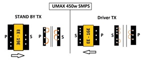
Now I have doubt on Stand BY Transformer Marked with part No. EE-19E. Removed Transformer for testing.

As per My database it shows windings in different way. Again I got confusing moment like I always say never trust on Standard Color code of Wire used in the circuit. Same way I found about this Transformers. Sharing my old article link for your reference: https://jestineyong.com/some-confusion-about-transformers-in-atx-smps/
For confirming doubt I also removed Driver Transformer marked with EE-16E code to see winding of the terminals.Here also I got some different windings on pins.

Checked with the multimeter, winding showing exact as per the above diagram. I checked other transformers also with same marking which I salvaged from some old SMPS. Marking code are same but most of them are having different winding pinouts so it is confirmed every manufacturer having their own design of these Transformers hence never assume same pinout.
Almost everything is checked in standby circuit so where is the problem? again removed switching transistors for testing the Mosfet.
Here I applied New trick for MOSFET Testing Using LED. Connected LED Drain to source and connected it on 3v Supply & try to trigger it by giving signal on gate but LED is Not glowing on trigger.

It is confirmed that the MOSFET is not turning on (it was showing OK earlier when I checked with a multimeter). When I tried 4 to 5 times, it turned ON only once. Indicates MOSFET works intermittently.
This MOSFET number is P3NB80 as per the datasheet it was 2.5amp/800v.
I looked in my storage box but couldn’t find. I checked some SMPS diagrams of similar wattage they used 2N60 Mosfet. I found one in my storage box before replacement I checked it with above method.


& found this Replacement MOSFET is Proper working I triggered it ON/Off multiple times. For testing i Replaced the MOSFET in the circuit.
After replacing MOSFET I connected SMPS to Series Test Board & after applying power I checked Standby voltage. On purple wire & I found +5V. then I triggered the SMPS on by shorting PS_ON (Green wire) to Ground.

Now fan start spinning & I tested respected working voltage like 3.3v, +5v, +12v all are in working range. Assembled everything back, now SMPS is ready for pickup.

This article was prepared for you by Yogesh Panchal who works as a Computer Hardware Engineer in Mumbai India.
P.S- Do you know of any your friends who would benefit from this content that you are reading now? If so, forward this website to your friends or you can invite your friends to subscribe to my newsletter for free in this Link.
Note: You can check his previous repair articles on Creative SBS 240 PC Speaker Repaired
 (34)Dislikes
 (0)
(0)
17 Comments
Leave a Reply


Parasuraman S
September 28, 2025 at 5:37 pm
Excellent professional fix, with step-by-step explanations! Many thanks for this valuable article!
Yogesh Panchal
October 8, 2025 at 9:04 pm
Thank you! Sir
Ajay Kumar
September 28, 2025 at 6:21 pm
Nice to read about the detailed way of testing SMPS components. I have a few dead SMPs, your article has encouraged me to undertake the repairs of these items. Thank you
Yogesh Panchal
October 8, 2025 at 9:05 pm
Ajay Kumar,
Thanks! for your encouraging words
Waleed Rishmawi
September 28, 2025 at 6:40 pm
thanks for the info, I never borthered to fix this kind of power supplies because they are too cheap in my hometown..thanks for sharing and have a blessed day
Yogesh Panchal
October 8, 2025 at 9:06 pm
Thanks! Waleed
Albert van Bemmelen
September 28, 2025 at 7:59 pm
Since these higher power rated ATX smps units still are quite expensive these days fixing them is completely worth it! Thanks for sharing this detailed repair Yogesh.
Waleed Rishmawi
September 29, 2025 at 11:31 pm
Albert: in my home town they are very cheap to buy…so not bothered to fix them. Have a blessed day
Yogesh Panchal
October 8, 2025 at 9:06 pm
Thanks! Albert
tree
September 28, 2025 at 8:38 pm
Excellent repair
Yogesh Panchal
October 8, 2025 at 9:07 pm
Thanks!Tree
Mark J
September 29, 2025 at 12:08 am
Yogesh good article. Very detailed.
Yogesh Panchal
October 8, 2025 at 9:08 pm
Thanks! Mark J
Andy Shiekh
September 29, 2025 at 12:10 am
Surprised that such small bridge rectifiers could handle 450W even if it is 220V only supply.
Yogesh Panchal
October 8, 2025 at 9:11 pm
Andy Sheikh,
Load is always handled by switching Transformer & PWM circuit.
Ronald
September 29, 2025 at 6:37 am
I very much appreciate the advice on checking mosfets. You are a fine technician. Thanks.
Yogesh Panchal
October 8, 2025 at 9:09 pm
Thank you! Ronald