
What’s The Purpose Of Two Different Type Of Capacitors In Parallel?
Repairing Switch Mode Power Supplies (SMPS) can be much fun, interesting but sometimes you may get frustrated too if it can’t be repaired. There are simple and complex designs of SMPS in the market. Problems of SMPS can be:
- No Power
- Low Output Voltage
- Too high output voltage
- Shutdown Upon Turning On (due to too low or too high the output voltages)
- Power cycling/pulsating
- Run for sometimes (probably from few seconds to couple of minutes) and then shutdown
- No Standby Voltage
- Burnt components in either primary or secondary side
- etc
Before you start to repair any SMPS, obviously understanding how a SMPS work will give you a good advantage in tackling the problems. You will know which area to start checking for the faulty parts instead of wasting time checking on all the components. If the component’s density is high, it will waste you lots of time trying to find out the bad components espeically in a compact area. So, understanding each section of the function of SMPS or to be more specific if you could understand each component’s function would be even better. Why? Because if there is a problem in the SMPS, you will know where to start troubleshooting it instead of guessing where and how to start finding the bad component.
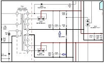
In the example below, I will just explain one of the functions of component in SMPS. Ever wonder why certain SMPS have two different type of capacitors in the DC output filter circuit and to some are using only one type? If you compare both schematic diagrams in figure 1 and 2 below, you will find that in figure 1, beside the electrolytic capacitor (C906 2200 uF 16V) you will also see another capacitor (non-polar 0.22uf) that is connected parallel in the same DC output line. Look at the small arrows:

Figure 1
If you look at figure 2, you can’t find any non polarity capacitor in the DC output line. You could only see two electrolytic capacitors connected parallel but separated by the inductor L201.
Figure 2
Why not all DC output have the same common designs which is to have one electrolytic type and one non polarity type of capacitor? Well, it depends on the manufacturers, by right a good and reliable SMPS should have two different types of capacitors in the DC output line. For your information, the non polarity capacitor can also be installed in the load/mainboard area. Now, you may ask, what’s the different between the two capacitors since the common function of capacitors is to remove the ripples and to store current?
Here is the reason why:
- Electrolytic capacitor- handle low frequency ripple and mains noise and major output load changes (act as reservoir to provide load current during the negative cycle of rectification process)
- Non-Polarity capacitor (usually is ceramic type)- handle noise (high frequency) and fast transients. That means it reduce electromagnetic interference (EMI) that result from switching noise.
Now you know that both capacitors serve different functions in the DC output filter circuit. What about the common problems that these two capacitors can cause in the power supply?
Electrolytic capacitor– Usually bulged, leaked and have high ESR ohm. The capacitance value will run also. It can go shorted too but quite rare. These problems can cause the power supply to produce lower than normal DC voltage on that particular DC line, the power supply will pulsate, shutdown and etc. If it is shorted, the power supply can’t be turned on due to large current draw by the capacitor to ground.
Non Polarity Capacitor– Hardly fail. Even if it fails, the capacitance value would be out and have very less effect (impact) to the power supply due to that it may not be a significant component. If it is shorted then it would have the same implication like what a shorted electrolytic capacitor can do to a power supply mentioned above.
Conclusion- Every component in an electronic circuit be it in SMPS or motherboard/mainboard has their own functions. This is why, when you want to find replacement, the best is to get back the same type or part number to avoid unnecessary weird symptom in the device you are repairing. Removing a particular component from a working circuit may or may not have a direct impact on the circuit. It is all depends on how significant or the role the particular component is playing. For example, if you remove the electrolytic capacitor from the DC output line, the effect will be the DC line voltage will become low (because there is no storage current (reservoir) to supply to the load) or even will cause the power supply to shutdown (because abnormal voltage will be detected by the optoisolator IC through the feedback/regulation circuit).
However, if you remove the non polar capacitor from the DC output line, it does not affect the DC output voltage at all because the function of the non polar capacitor is not to store the much needed current by the load, in fact the function is more toward to help in reducing the noise in the DC output line. Being said that, if the load itself already have a built in non polar capacitor then without the non polar capacitor in the DC output line will not affect the performance of the power supply at all. I hope you have gain some new knowledge in this article and you are welcome to comment related to this topic. Ok will see you again in the next repair article.
This article is brought to you by Jestine Yong. He is from Kuala Lumpur Malaysia and he loved electronics repair and blogging about electronics repair information. He is the author of the famous SMPS repair ebook and also a lecturer and conduct electronics repair courses at Noahtech Electronics Training Center.
Please give a support by clicking on the social buttons below. Your feedback on the post is welcome. Please leave it in the comments.
P.S- If you enjoyed reading this article, click here to subscribe to my blog (free subscription). That way, you’ll never miss a post. You can also forward this website link to your friends and colleagues-thanks!
You may also interested in his other repair article on How to Test LCD Inverter Transformer
 (97)Dislikes
 (2)
(2)
52 Comments
Leave a Reply


Anwar Y Shiekh
September 16, 2021 at 9:25 pm
There is also the nice trick of two equal electrolytics in parallel, as capacitance adds, but the inductance is reduced, so improving high frequency performance.
Jestine Yong
September 17, 2021 at 12:54 pm
Hi Anwar,
Thanks for the info. There is also an info about the first cap (before the inductor) is to act as reservoir and the second cap (after the inductor) is to smooth out the ripples but the different is both have different capacitance values.
Jestine
Jacques
September 17, 2021 at 5:45 pm
Such a humble explanation of how these caps work. That's what distigiuses men from boy's...their humbleness, like yourself. Thank you very much.
Eric Rice
September 16, 2021 at 9:32 pm
Thank you Jestine! Good article, please do more like this!!
By the way, the induction coil in the first schematic pretty much does the same thing as the ceramic capacitor. Induction coils in dc circuits resist change which would also level off the high frequencies, but with a disadvantage of space, weight, and additional cost.
Cool stuff, thanks again,
Eric
Jestine Yong
September 16, 2021 at 9:55 pm
Hi Eric,
You are absolutely correct! But in some designs, it does not have the inductor at all.
Jestine
Nate like
September 16, 2021 at 9:33 pm
You are one of the best people because you provide benefit and good to people
Rodger Hopkins
September 17, 2021 at 6:08 am
Jestine, Great article,and informative as all ways.
Rodger R
Jestine Yong
September 17, 2021 at 7:48 am
HI Rodger,
Thanks.
Jestine
Gabriel Ogunleye
September 16, 2021 at 9:40 pm
Thank you very much, sir. I really enjoyed your tutorial. Please, I would like to ask you a question.
How can I locate the circuit controlling the switching on/off either by remote control or by using button in any tv? Thanks
Jestine Yong
September 16, 2021 at 10:06 pm
Hi Grabriel,
You are welcome. If you have the schematic diagram you can track from one of the optoisolator ICs. The main incoming On signal to the LED diode of optoisolator IC is coming from the MCU IC. In order for the MCU IC to send out the On signal, it must get signal either from the front push button or from the remote receiver circuit. The MCU also must have the standby voltage first before it can do its job. Once the optoisolator IC phototransistor is energized the whole circuitry in the main power supply section will begin to function thus producing all the output power to the mainboard.
Jestine
Gilberto Galindo
September 16, 2021 at 9:52 pm
Thanks for share all that info. Sometimes we make repairs the blindfold way as a parrot that "speaks" but, learning how to do, not is only easy, but better.
Gracias por toda la información que nos has compartido en estos años. Desde México saludos y ¡Cuídate!
Jestine Yong
September 16, 2021 at 10:12 pm
Hi Gilberto,
You are welcome.
Jestine
Albert van Bemmelen
September 16, 2021 at 10:05 pm
Good to know that the sort of design is very much manufacturer dependant!
I know that those non polarity capacitors also can be found in Tube luminescence lights, energy saving lamps and other circuits right on the phase and nil primary power input lines. Obviously for the same purpose to eliminate the device emitting any jamming frequencies back onto the power lines. And they say that the in the Tube Lumnescance Lights added capacitor is also to improve the cosinus Phi factor. Which effect can be visualised with a fast digital camera by filming the lights.
Jestine Yong
September 16, 2021 at 10:11 pm
Hey Albert,
Thanks for sharing this.
Jestine
Babu M S
September 16, 2021 at 10:35 pm
Sir,
Very useful information your given in this article.Please give many more.
Thank you very much.
Jestine Yong
September 17, 2021 at 7:50 am
Hi Babu,
You are welcome.
Jestine
Henrique J. G. Ulbrich
September 16, 2021 at 11:52 pm
Thanks for this useful information.
Jestine Yong
September 17, 2021 at 7:50 am
Hi Henrique,
You are welcome.
Jestine
Tyrone Arendse
September 17, 2021 at 12:23 am
Thank you for the information regarding the capacitors
Jestine Yong
September 17, 2021 at 7:51 am
Hi Tyrone,
You are welcome.
Jestine
Abdullahi
September 18, 2021 at 5:17 pm
Very interesting piece of information, easily understood.
I would cease the opportunity to ask a question myself.
I have a power supply in an electronic device
I don't have the diagram though.
I can see the step-down transformer,
But after the rectification diodes,
I can see two ceramic 400v, 1000uf capacitors after the inductor, I can see one leg of the ceramic capacitors connected to a transistor, and voltage regulator ic switcher 1432.
But when the initial ac from network supply goes low, and fluctuates for long, the voltage ic switcher gets damaged (bursts from its centre) . And the device shuts down.
Once replaced with a new ic, the device comes up.
Could it be damaging because of the fluctuation? (but the capacitors are there)
Or because of poor heat sink?
Jestine Yong
September 20, 2021 at 12:26 pm
Hi Abdullahi,
Yes possible the fluctuation had caused the IC to burst. This is why many people use AC voltage stabilizer for their equipment if they found that their incoming AC is not stable. Not only the IC can burst, if the fluctuation is too great, the power primary side components can also breakdown. The capacitors are there in the filter circuit is not to solve the fluctuations problem caused by the unstable incoming AC voltage. The capacitors are there to filter off noise (low and high frequency) and to supply the stored current when the load needs it. And it has nothing to do with the heatsink. Even with bigger heatsink and if the fluctuation is very great, the IC may still burst. Solve the unstable incoming AC problem and all the electronics circuits/components down the line will be very happy.
Jestine
Alex Obara
September 17, 2021 at 1:00 am
It might be very true because I see those ceramic caps so often in the secondary sides of many smps.
Thanks so much, Mr Yong
Jestine Yong
September 17, 2021 at 7:49 am
Hi Alex,
You are welcome.
Jestine
Yogesh Panchal
September 17, 2021 at 1:06 am
Sir,
Thanks! for sharing info.....I seen in some laptop charging adapter manufacturer is using non polarity cap between Neutral line on primary side ground and on secondary side ground and through dc pin it will get connect to most of chassis/body ground & cause electrical shock /current on laptop body metal parts some time even on the body made using aluminum type alloy.is that because of "Fast Transients"??
Jestine Yong
September 17, 2021 at 12:45 pm
Hi Yogesh,
The capacitor that is connected between the live and the neutral line is called as 'X' capacitor. The function is to to protect against differential mode interference so that noise would not be channel to the power supply circuit. The capacitor that is connected between the hot ground and the cold ground is called as class Y' capacitor or line to ground capacitor. The function is to reduce or bypass electro magnetic interference (EMI) currents from the primary side to secondary ground. If there is leakage in this capacitor it may cause some minor electrical shock when you touch on the device's metal part. The electrical shock can give you unpleasant feeling and it has nothing to do with the fast transient. Try check this capacitor and if possible just direct replace it and retest. To check this capacitor leakage you need an insulation tester. If there is a design problem you might still get a minor electrical shock even though the capacitor is tested good.
Jestine
Mihai
September 17, 2021 at 2:06 am
Hello sir,
Thank you for sharing information !
Jestine Yong
September 17, 2021 at 7:49 am
Hi Mihai,
You are welcome!
Jestine
Robert Calk
September 17, 2021 at 6:21 am
Nice lesson! Thanks, Mr. Yong.
Jestine Yong
September 17, 2021 at 7:48 am
Hi Robert,
You are welcome. Good to hear from you again.
Jestine
Mark
September 17, 2021 at 7:49 am
Excellent article Jestine,
Thanks for sharing.
Keep them coming!
Jestine Yong
September 17, 2021 at 12:06 pm
Hi Mark,
You are welcome.
Jestine
Parasuraman S
September 17, 2021 at 8:03 am
Great and very useful tips! Many thanks for sharing! All the very best to you!
Jestine Yong
September 17, 2021 at 12:06 pm
Hi Parasuraman,
You are welcome.
Jestine
sunil gamini ratnasingha
September 17, 2021 at 11:23 am
This is very important to technicians for those who have no theoretical knowledge in electronics but very important in understanding how and why it is there. you are right.
Jestine Yong
September 17, 2021 at 12:08 pm
Hi Sunil,
It is always good to have some theoretical knowledge to speed up the repairing work.
Jestine
Waleed Rishmawi
September 17, 2021 at 3:13 pm
it has been a long time since we read an article from you. You have a very good informative style that makes everything looks easy and simple to understand. thanks for sharing this article. have a blessed day
Jestine Yong
September 17, 2021 at 4:47 pm
Hi Waleed,
Yes indeed very long time already. Glad that you liked the article.
Thanks.
Jestine
Aword Stephen
September 17, 2021 at 10:34 pm
Thanks,jestine this open mine eyes to a lot of others things,thank you thank you
Jestine Yong
September 17, 2021 at 10:36 pm
Hi Aword,
You are welcome.
Jestine
Jun
September 19, 2021 at 11:26 am
Thank you Very much, Sir Yong, I am glad you always be here updates giving Ideas or tricks God bless
I hope Someday I will buy your Ebooks this Coming if I get Monetization of my youtube channel.
Jestine Yong
September 19, 2021 at 7:28 pm
Hi Jun,
Thanks for the support.
Jestine
Eugene Staglon
September 22, 2021 at 1:34 am
Thanks Jestine for this very informative article and all the tips in the comments.
Jestine Yong
September 22, 2021 at 10:31 am
Hi Eugene,
You are welcome.
Jestine
Hardy
September 25, 2021 at 4:48 pm
Nice article I really like it
Jestine Yong
September 25, 2021 at 6:53 pm
Hi Hardy,
You are welcome.
Jestine
Andrea Del Corso
September 26, 2021 at 8:01 pm
Come al solito,ottimo articolo!Complimenti!
=====================================
As usual, great article! Congratulations!
Jestine Yong
September 27, 2021 at 11:08 am
Hi Andrea,
Thanks.
Jestine
Joven Urbano
September 30, 2021 at 12:02 am
Thank you for the additional knowledge gained.
Jestine Yong
September 30, 2021 at 10:39 am
Hi Joven,
You are welcome.
Jestine
Humberto
October 12, 2021 at 11:51 pm
Very useful information collected in this article.
Jestine Yong
October 13, 2021 at 3:43 pm
Hi Humberto,
Thanks.
Jestine