
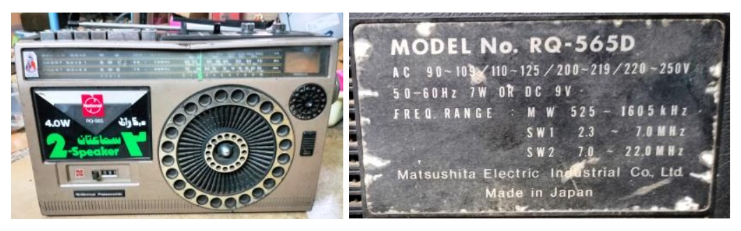
The Story Of ‘ORGAN’ Transplantation To Save A Lovely Antique NATIONAL PANASONIC RQ-565D 2-IN-1
This set was one among the two sets brought by a new customer from a faraway distance due to person to person publicity that takes place when we ensure total commitment and involvement in any work that we undertake without bothering about the monetary benefits. Three screw holes were already broken in the set by a previously attended technician as the heads of the screws were rusted and lost the grip. The condition of the set can be guessed from the following pictures of the inside when I opened the set.
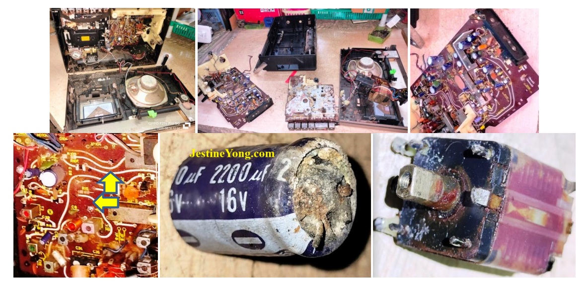
This is a set in which NP had introduced carbon resistor printing on the board which can be seen on the third and fourth pictures above. The white paint what you see is on top of the carbon prints which are either long jumper wires or leads of the carbon resistors printed. I have marked just two resistors which are printed and value of these cannot be read unless we have a circuit diagram! Even jumper and inter connecting wires are carbon printing with white protective paint on top of it. You can see them going all over like a snail’s tracks! A few such long printed wires showed resistance by a few ohms such as 24 Ohms. But the design might have taken care of the resistance to compensate and match the impedance, which is what actually matters! The fifth and sixth picture above would show you the condition of the components found. The gang was rusted and the previous techie had tried to clean it using some spray, which made it worse, as these are PVC gangs! The trim pots at the rear were also rusted and spoiled. So, you can guess what kind of work I took it up this time!
I began the restoration work from the AC in to DC in and ensured that the required voltage (9V as written on the rear side of the back cover) was present. The set showed signs of life as some noise came to the speaker after I cleaned & lubricated the switches and replaced the electrolytic capacitors in the PS region and applied power to check that. So, I went ahead and replaced the rest of the E Caps and retouched the solder points on the rear side. We can use only some gentle brushes to clean the board and should never use PCB cleaning sprays or WD40 that could cause obliteration of the printed tracks and carbon resistors. Even the lubrication done on the switches should not spill over! My hunt for a replacement gang that would properly fit in to fix the dial drum and its cord, was in vain and weeks passed. The tape mechanism was totally rusted and spoiled and was beyond restoration. I was keeping the customer informed of the work done and progress made regularly by way of images, videos and voice messages in Whatsup. One day he called me to enquire whether one similar set lying with him can be used to remove the gang from it as that was declared spoiled and lying discarded. He brought it one day as per my request and I was surprised to see the similarities of the designs.
On opening the set, I found that the board, circuit and even mechanism were exactly same, though the model of this set was RQ-547D. The customer told me to use parts from this to make the set under repair, work very well. I transplanted the gang, upon which the radio stations were picked up, though with crackling noises and disturbances. As I had a reference board, I compared the values of the printed resistors and found a couple of them corroded at the joints.
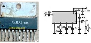
Scraped the remaining tracks and fixed through-hole resistors of same value in place. I replaced all the fixed caps in the Amplifier section. Even then the crackling noise could not be solved. Since this noise was present even when the volume control was at the minimum, the problem was indeed at the power amp section. Then I transplanted the Power Amp IC, BA524, the datasheet of which was not available for download. But I got an image of it after searching it in many places and I give that here for future reference:
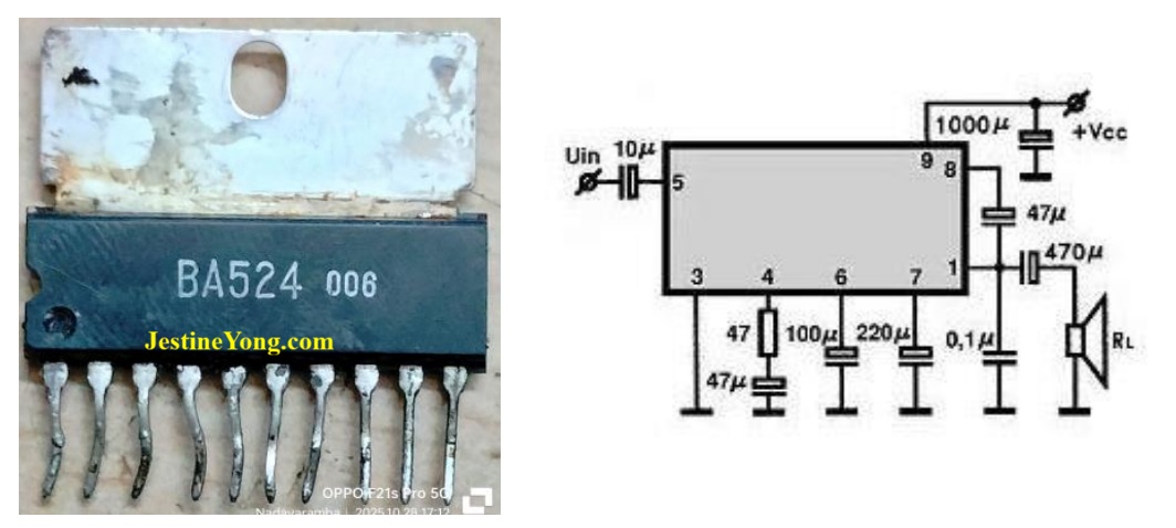
The difference in the circuit on the board was (1) pin 5 was connected to 6 with a 98K reading resistor and a signal diode (cathode connected to 6) in series (2) Pin 6 and 8 were interconnected through a resistor of 12K. As these two resistors were corroded at the joints, I scraped it off and connected through-hole resistors in place. I used 100K instead of 98K as I suspected that the value of the resistance would have dropped due to corrosion and loss of carbon. This type of problem is peculiar to such sets. The reading of ohms on the track that came to pin 5 was same in both the sets and I left it like that without connecting an external wire. The crackling noise got solved with these rectification works done and the radio was working superbly well picking up almost all stations. Then fixed the dial drum and cord and copied the method used in the other set to route the cord and fix the needle. Then turned my attention to the mechanism. It was clean and found to be working very well when power was applied. It used a mechanical motor without any regulator board inside and it was large in size too. The motor was found dragging and there was no way of adjusting the speed.
So, I replaced it with a new one from stock; 9V CW type, which had a speed regulator built in. The testing of the mechanism was done keeping the board outside, which can be seen in the following picture, which was taken before replacement of the motor:
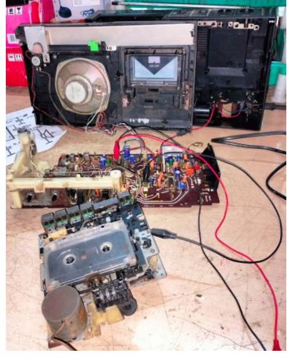
I adjusted the speed of the new motor by playing a cassette and listening to the familiar songs for its pitch and tone and voice of the singer. I had already cleaned the mechanism using IPA and adjusted the head for a peak, noiseless output.
Then fixed the board back with its umpteen numbers of screws and the mechanism in place. In the process of checking the sets, the inter connecting wires between the PS board and mother board got snapped a few times, upon which I provided a wire with a slip on connector in the middle, which was a salvaged speaker wire from LCD TVs. You can see that connector in the above picture. Then the wires to the leaf switch on the mechanism snapped. I had to then remove all the screws and take out the board to provide a similar connector with a different wire colour in order not to make a mistake while doing the interconnections in future. The whole work, though look simple when described, took several precious hours in different sessions for weeks! Finally the set could be assembled back after completion of tests and here is the picture of the components replaced, the survived jolly patient & the body of organ donor by its side (LOL)
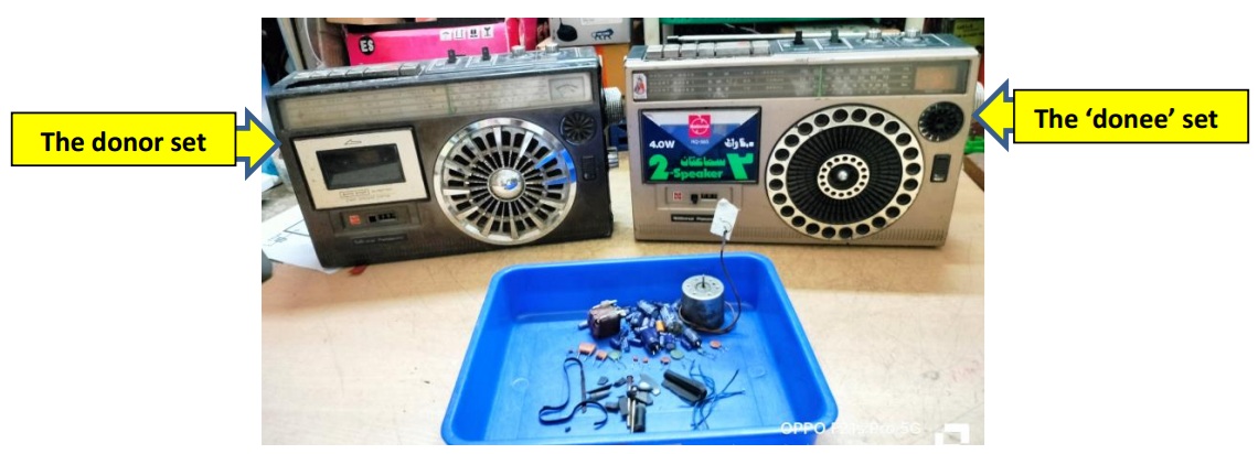
(A payee is a person who gets paid, is it not? Then why not we add this ‘donee’ to the dictionary to indicate the one who received a part from a donor? (English lovers: Please don’t take your stick! I am a mischievous boy still!) (LOL).
While pasting the picture in the article, I felt that I could have replaced the dull looking signal level meter too! May be on a future return, which is quite possible, I can do that! Thus the integration of two 2-in-1s to make one 2-in-1 ok was accomplished with aplomb and the derived immense satisfaction of this ‘doctor’ got collected to its bag without fail!

This article was prepared for you by Parasuraman Subramanian from India. He is 76 years old and has more than 30 years’ experience in handling antique equipment like Valve Radio, Amps, Reel Tape Recorders and currently studying latest tech-classes conducted by Kerala State Electronics Technicians’ Association. He has done graduation in BBA degree, private diploma in Radio Engineering and retired as MD of a USA company. Presently working as Consultant to Hospital and other institutions.
Please give a support by clicking on the social buttons below. Your feedback on the post is welcome. Please leave it in the comments.
P.S-If you enjoyed reading this, click here to subscribe to my blog (free subscription). That way, you’ll never miss a post. You can also forward this website link to your friends and colleagues-thanks!
You may check on his previous article on Third Visit Of Videocon LED TV Model V-3218 With Picture Freezing Problems
 (36)Dislikes
 (0)
(0)
10 Comments
Leave a Reply


Mark J
May 23, 2026 at 9:35 am
Parasuraman great job on the repair and restore. You inspire me to take on restorations of these old sets. Thank you for sharing.
Parasuraman S
May 23, 2026 at 10:35 am
Restoration of such antique sets is always a thrill! Many thanks for your comments, dear Mark!
How I wish like-minded people like us could meet in one place for a get together! Unfortunately, I am now not in a position to undertake any travel mainly because of my wife's condition and secondly the financial burden due to soring medical expenses has curtailed any extravaganza!
Mark J
May 24, 2026 at 2:30 am
I understand how you feel Parasuraman. I wish there where more forums like this one. It would be nice to meet like-minded that share the same passion for restoring these old sets.
Parasuraman S
May 24, 2026 at 8:14 am
Many thanks, dear Mark!
Albert van Bemmelen
May 23, 2026 at 4:10 pm
Although the shown amplifier BA524 image was helpful it only showed 9 pins whereas your BA524 actually showed 10. But here in the compendium collection book you will find your exact BA524 amplifier!
https://www.griederbauteile.ch/download/Manuals/5000-IC-Power-Audio-Amplifiers.pdf
Yogesh Panchal
May 23, 2026 at 5:43 pm
Albert, thanks! for sharing link for reference
Parasuraman S
May 23, 2026 at 7:31 pm
It shows only 8 pins and not 9 pins as mentioned by you. I think pins 2 & 10 are not used. Even in page 42 of what you sent, BA524 does not show pins 2 and 10. Many thanks for your expert comments, dear Albert!
Yogesh Panchal
May 23, 2026 at 5:42 pm
Good Job! Sir
Never heard of carbon resistor printing on the board before.
Now a days Most of Repairs depends on Donner Devices, because you can't get reliable material in the market or unavailability of materials.
Parasuraman S
May 24, 2026 at 8:16 am
Yes, but storing the doner devices, occupies our storage space and that is a menace for people like me, who operate from home! I get such donor device boards as and when required, instead of storing them, though I do have some collected. Many thanks for your comments, dear Yogesh Bai!
Hans Andersson
June 26, 2026 at 3:16 pm
Like a miracle resurrection from dead.