
Solved Red Light Blinking Problem In Eureka Forbes Euroclean iClean Vacuum Cleaner
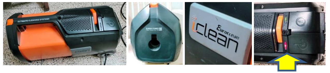
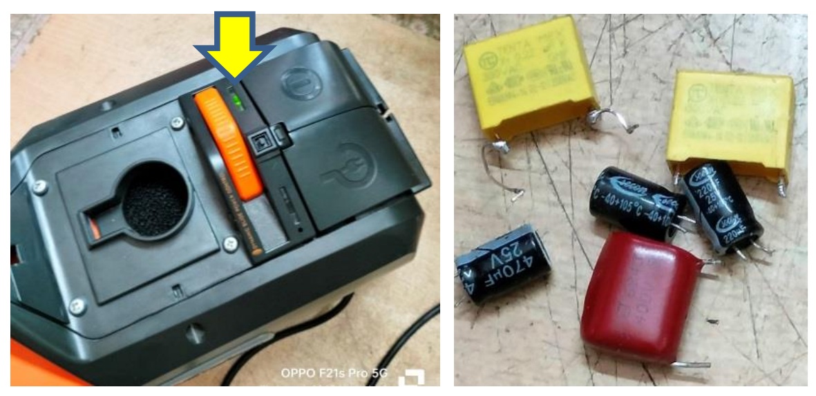
This vacuum cleaner was brought by one of my old regular customers with the complaint that the motor starts but immediately stops with a red light blinking (please see last image above with yellow arrow marked). My first duty is to always open and clean the inside, though this time it was a cleaner itself for a change. Let me explain a bit about the connections and circuitry before I share the images of this complexly wired circuit board. The long AC wire is wound on an old wall-clock-like-type spring loaded spindle with a clutching ratchet to hold it from getting rewound, the Line-in wire of which is going to the on/off switch & to the board, with a direct tapping to the mains board. The Neutral wire goes directly to the mains board, which actually serves as its ground too! The Red wire from the on/off switch goes to a thermal sensor that is fit on the rear cover of the motor, and from there the red wire goes to the mains board.
The direct tapping from AC Line-in goes to a series of resistors across a 0.22uF 300V AC X-type capacitor, at the end of which there is a rectifier diode and a 470uF/25V capacitor to provide a startup voltage to the main IC, 8S003F3. Why is it directly connected like this? Since the mains input goes to the motor controlled by the Triac, a large amount of current is drawn at the start up. So, if main IC is to get voltage only after switch on, it might not get the required voltage/current to take up control and it might malfunction or even fail. The line-in that is routed through the on/off switch that goes to the board is once again dropped through a 684/400V capacitor and series resistors, smoothed by a diode and an electrolytic capacitor with a 5V Zener at the end. That 5V is fed to a three pin 1.8V regulator IC which provides the secondary voltages required for function of the main IC. The Line-in also goes to the Triac with its gate controlled by the main IC through a 470K (speed adjuster) sliding potentiometer. The Neutral wire is directly connected from the board to the motor. Now let us have a look at the images and a pin description of the main IC, which also gets a dropped AC directly from the Line-in for input voltage sensing.
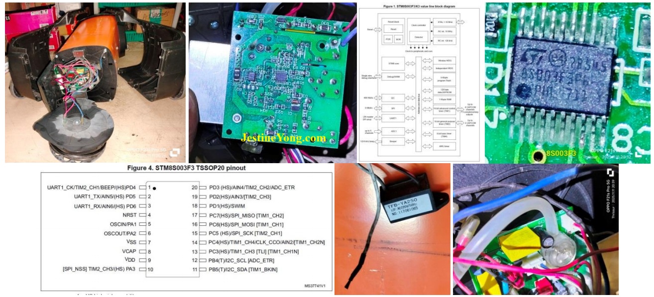
I did not give a picture of the board from the top, as it would be of no use. Wires are going crisscross obliterating clear view of components fit. This main IC datasheet runs to 103 pages! It has built in memory, crystal, DC-DC converter etc.
The last but one picture is that of TFB-YA250 which is a negative ion generator and functions if selected by a switch available in-between the power on and cable release switches. The yellow LED will light up on selection of this. In the last picture above, you can see a component which looks like a small tank with a tube. The tube was found inserted to a small hole that reaches the inside dust collecting chamber. If the sucking is blocked with excess dust collection, the pressure built in will suck the air from this tube, which will pull the diaphragm attached to it inside that component, which will cut off the AC input for the secondary 5V generation. Then the red light will flash indicating excess blockage.
The datasheet of the main IC can be downloaded from the following link:
https://www.alldatasheet.com/datasheet-pdf/pdf/1277739/STMICROELECTRONICS/8S003F3P6.html
Having explained the main function of this device, let us now focus on the trouble shooting done and remedies provided. First and foremost was checking the dust chamber and find out whether there was any blockage. It was clean and neat and with a fresh dust collection bag in place. The second step was to check the vent of the tube and ensure that it was not blocked due to some dust. In order to do that, I had to remove the portion where the motor was fit. Let us have a look at the relative images:
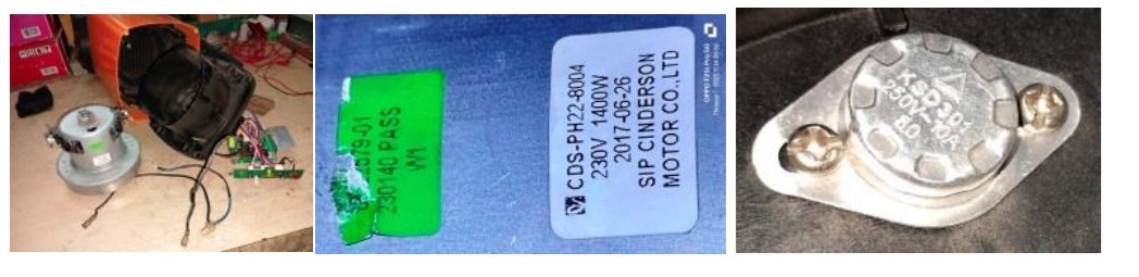
The first picture above shows the motor taken out from the housing. Second image would show you the model number, voltage and wattage of the motor. The third picture is that of the temperature sensor fit inside. The vent was clean and the tube also was clean. So far so good. The next step was to check whether the IC was getting the correct 5V inputs. The startup voltage has to be ok, as the green signal on switch on is seen. Nevertheless, I checked it up and found it to be around 4.86V. The secondary voltage of 5V was not stable, as it dropped after a few seconds, upon which the red light started blinking. So, there was the problem. As mentioned by me earlier, the 5V is generated through a 684/400V cap along with a few resistors in series, which is a very cheap way to drop voltage when the current drawn is not high. I removed the cap and checked and see yourself what was the reading:
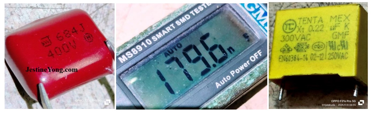
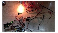
As you can see, a 680nF cap was showing 179.6nF which is a short. Luckily, because the current drawn was very negligible, no severe damage had taken place. I replaced this with a 680K/400V cap for continuing my checking and later I replaced it with an 800V cap. Then as a routine I also checked the 0.22uF/300V AC X type cap that provided the startup voltage (Please see third picture above). The value indeed had changed. There was a similar yellow cap connected as an EMI filter in the AC input section. I removed it and checked and found that the reading was better. So I interchanged these caps, as I was not having exact replacement in stock and ordered for it online. These types of X caps are not easily available in the local market. As a routine, I also changed the 470uF and two 220uF electrolytic capacitors. Then connected a 100W bulb as a load in place of the motor and checked whether the device was working without going to protection mode. You can see the result yourself:

I left it on for a few minutes and ensured that it was stable. Next step was to check the motor and its function visibly, looking at the contacts where the carbon brushes touch the various windings on the rotor. As I was not able to handle this alone, I took it to my techie friend who runs a shop exclusively handling washing machine, AC, Refrigerator, Microwave oven and other such home appliances. He takes up jobs only from the technicians and not directly from the customers. So, you can see only the boards there and not large appliances. He took the motor in his hand, held it tightly in place with a large plier, after giving the input wires directly and held it high so that the motor does not jump of when power is applied. He held the motor at an eye view level and applied the power. He observed the sparks generated and the running of the motor and said that the motor was running perfectly without any jerks or stops or strains and gave a clean certificate. I thanked him and returned home and fit the motor back in its place, duly inserting the dust sensor tube in its slot. Then connected the circuit and applied power through the multimeter to check the Ampere drawn, result of which can be seen in the following picture:
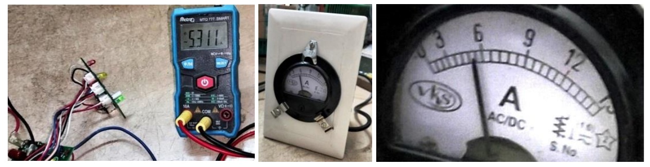
As you can see, the reading was 5.311A (AC) which was well within the specifications. The motor showed 1400W for working at 230V, which meant that it can draw a current of 6.087A (Watts divided by Voltage). The regulator potentiometer was put at maximum for this checking. Incidentally, I noticed that the pot was making intermittent contacts. This type of 2”, 470K pot, with a lengthy knob was not available in the market. So, I opened it and cleaned it with IPA first and applied switch cleaning oil, upon which the function was ok, though not to the fullest satisfaction.
After receipt of the X type caps, I replaced the two caps on the board and fit it back and fixed the AC cord collection unit in its place. The on/off switch and indicator board was also fixed back where it was. After ensuring that all connections were in proper place, fixed the outer covers and ran the Vacuum cleaner for some time and ensured that it was functioning properly. I put my hand and blocked the sucking vent in quick successions to check the power and it was found ok. The throw at the exit end was also equally powerful. I made a switch box with a three pin plug and on-off switch with extended wire and a three pin top and fit an Analogue Ampere meter on the other side. This is very useful for checking the current drawn by a device. The second picture what you see above is the reading shown by the Ammeter when I checked the Vacuum Cleaner after fitting everything. I have taken an extract of the reading to provide the third image above, which matches with the digital multimeter reading! The parallax error should be taken to consideration while reading such meters and we should view it straight only. Can I say now that the mission was accomplished with a lot of satisfaction gathered which got added to the collection? Here is the picture of the green light to show as a proof of its working and that of the components replaced:

This article was prepared for you by Parasuraman Subramanian from India. He is 76 years old and has more than 30 years’ experience in handling antique equipment like Valve Radio, Amps, Reel Tape Recorders and currently studying latest tech-classes conducted by Kerala State Electronics Technicians’ Association. He has done graduation in BBA degree, private diploma in Radio Engineering and retired as MD of a USA company. Presently working as Consultant to Hospital and other institutions.
Please give a support by clicking on the social buttons below. Your feedback on the post is welcome. Please leave it in the comments.
P.S-If you enjoyed reading this, click here to subscribe to my blog (free subscription). That way, you’ll never miss a post. You can also forward this website link to your friends and colleagues-thanks!
You may check on his previous article on Prediction Of An Expert In This Forum Came True In SAMSUNG LED TV UA32FH4003R
 (33)Dislikes
 (0)
(0)
14 Comments
Leave a Reply


Lewis
June 6, 2026 at 5:59 pm
great work very thorough work.Thanks just caps it seemed.
Parasuraman S
June 6, 2026 at 8:38 pm
Many thanks for your comments!
Yogesh Panchal
June 6, 2026 at 7:13 pm
Excellent Repair!Sir,
Parasuraman S
June 6, 2026 at 8:39 pm
Many thanks, dear Yogesh Bai!
Albert van Bemmelen
June 6, 2026 at 7:45 pm
I guess that this vacuum-cleaner had no earth wire attached since its housing was entirely made of plastic/ABS? Only wondered why you wrote that the 680nF cap was showing 179.6nF which is not a short when it is not given as a resistance in ohmic value. It apparently was just a lower degraded nF capacitor now.
Parasuraman S
June 6, 2026 at 8:43 pm
Probably. The cap when used to drop voltage, such as we see in battery charging circuits in cheap Chinese made gadgets, it can cause problems like a short when the value drops. We might have come across many burnt cases due to this. That is what I meant, dear Albert! Many thanks for your expert observation and comments!
Mark J
June 7, 2026 at 2:55 am
Great job on the repair Parasuraman. There is nothing you can not fix.
Parasuraman S
June 7, 2026 at 8:21 am
Many thanks for your supportive comments, dear Mark!
Imoud.O
June 7, 2026 at 3:28 am
Have you repaired this type of vacuum cleaner before? for I was amazed how you break down in practical the circuitry of this device.i enjoy reading it,thanks sir
Parasuraman S
June 7, 2026 at 8:23 am
My techie friends do help me always. Secondly study the circuit and its function very well before we take up rectification. That is the watch word. Many thanks for your comments, dear Imoud!
Philip
June 7, 2026 at 5:13 pm
What aroused my curiositys magnitude tenfold, is the clear explanation that easily makes understood the concept of the generation of 5V that feeds a three-pin 1.8U regulator IC that links to the main IC. Hats off ! To you, 'CAPSman'.
Parasuraman S
June 7, 2026 at 8:36 pm
Ha! Ha! Many thanks, dear brother!
Philip
June 7, 2026 at 6:45 pm
Testing heavy motors in ones hands is a bit scary. The momentary motor hard-kicks through ones hands are not for the faint hearted, and neither are the ear-piercing sound of emitted fat sparks for scary souls. For some motors, I understand prolonged and unecessary repeated tests are highly discouraged out of the possibility of burning the motor armature coils, owing to high current draw.
Parasuraman S
June 8, 2026 at 4:20 pm
Yes, it is very scary when the motor is not fixed in a safe place. Thanks for your comments!