
Conversion Of CCFL To LED Backlight Done In PANASONIC TH-L32C22D
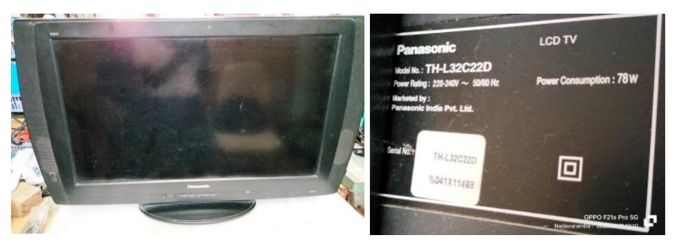
This TV was brought by a new customer as per recommendation of another to whom I had repaired a CRT TV long back. The complaint was that the backlight was flickering and even though he had taken to a technician a few times, it just worked only for a week or more and same problem was reappearing. This is an interesting piece of TV and I heard from our techie group that this particular model in this shape was only a few sold by the company. I applied power and confirmed that the backlight was flickering and after a few seconds, the TV was going to standby. Like a battery lid in the Radios, the back cover portion covering the housing of PS, Inverter and Mother Boards could be removed separately after removing 9 screws. Let us have a look at the inside:
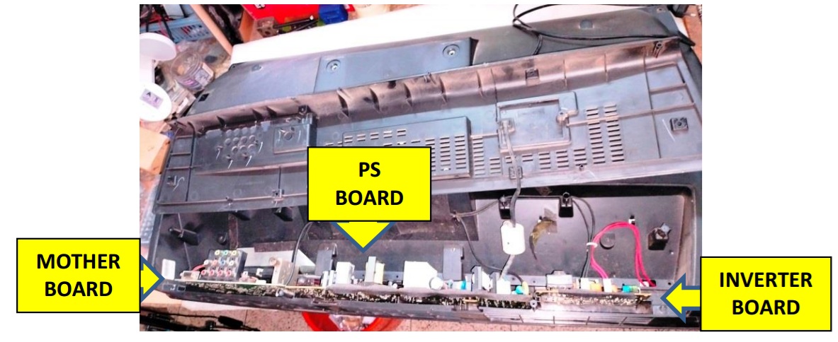
As you can see, the three boards are inserted into a slot/groove and it could not be accessed from the top like in most of the TVs. The mother board had the T-con circuit built in unlike the external board or in a scaler board. The LVDS cable was inserted into a socket located at the other end of the mother board. All the three boards were connected together with rigid connectors removing of which could not be done without taking out all of them together. All the three boards would have to be slid out simultaneously little by little from its tight grooves, without causing strain to the LVDS cable.
The back light connectors could be removed as these were located at the rear side. The connector of two speakers located at the sides, could also be removed from the MB. I slid out the boards ensuring that the interconnecting rigid connection wires are not broken and when the MB got out sufficient enough for accessing the LVDS cable, I opened its lock and slid it out very, very carefully not to detach the blue insert assist, as the cable was inserted into the socket from the bottom. Then took it out and cleaned the boards thoroughly. Let us have a look at the boards:
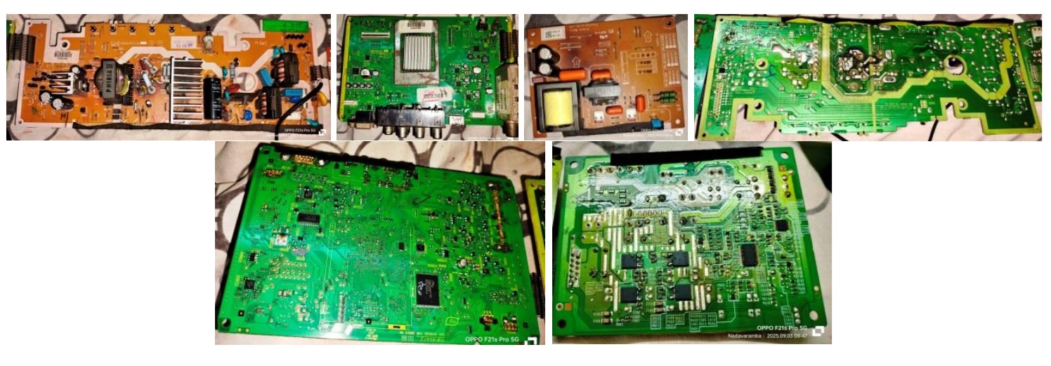
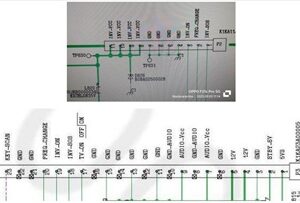
You can see the rigid connectors on the sides of the boards (see the picture of PS board, first one above). I downloaded its service manual from the website (https://www.manualslib.com/manual/1060232/Panasonic-Tc-L32c22.html) , without which servicing of such a set was extremely difficult. The power supply board had mainly three voltages coming out; 6V for standby, 12V for sub-supplies, 21V for audio and inverter. The PS board had a DC-DC converter IC to drop 12V to 6V. Let us have a look at the connectors from the PS Board:
The next step was to have a look at the backlight located under the panel. From the four thick wires; one red wire pair connector and one black wire pair connector, I could make out that the Lamp was CCFL. I mentioned to the customer that since the backlight problems are getting repeated, it was better to change it to LED, which he accepted upon an estimate given. After cleaning the inside of the board compartment and its lid, I dismantled the back cover and the front frame which had the speakers fit on the sides. I had to remove many screws as the TV was sturdy and a bit heavy. Let us have a look at the connected pictures:
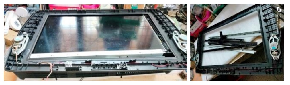
The panel was fit with two metal frames at top and bottom, which meant removing more number of screws. Then gently detached two scaler boards connected together with flexible strips, from its holdings on the side, taking care not to cause any tear or damage to the COFs. The panel had three side COFs too. Then moved the panel to a safe place (once again my son’s bed) cautioning my wife about it, which attracted remonstrance as usual! (LOL) Then removed yet another four frames from all sides that served as the bed for the panel. You can see all that in the second picture above.

Click here to check out Humphrey’s ebook on LED TV Panel Repair
The TV had a single CCFL in the middle with an oval shaped reflector. Let us have a look at this peculiar backlight:
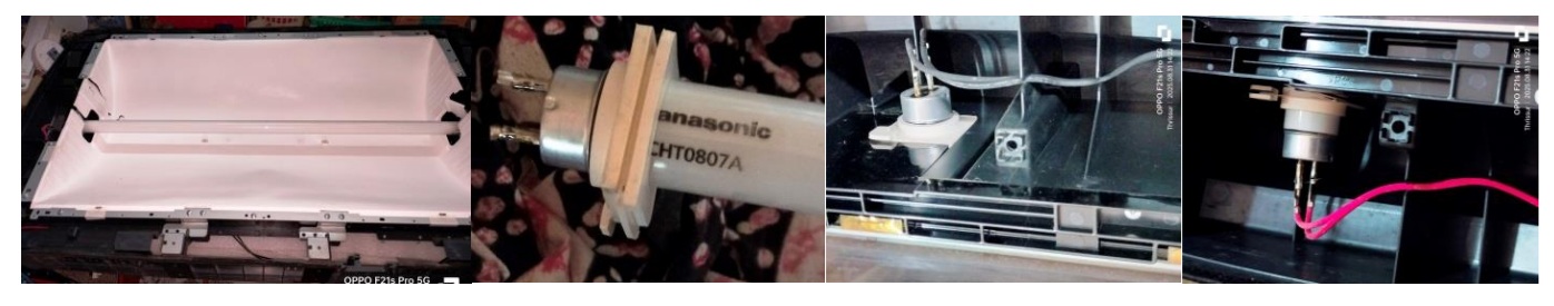
As the tube had become black on one side, the reason for flickering was evident. Perhaps the previous technician had put another tube from an old TV, as such tube was not available in the market. I could see soldering on the side wire inserts of the tube. That was to avoid loose contacts. Little did I realize the complication involved in fixing LED strips in an oval shaped surface! The reflector sheet had become so brittle due to heat that it had already suffered punctures in many places, perhaps from the previous service attempts, which you can see from its picture given above (1st).
First I wanted to make sure how much of light was required for which my techie friend suggested to get 3 strips of proper length with six 3V LEDs in each strip and try. He too was surprised to see the oval shape of the backlight cover. My interest gets aroused when others reach a dead end and I put this into the back of my brain for churning to find a solution. I fetched three strips and connected them in series, to control the current required, which means I had to find a source of 54V. I connected an LED inverter and tested it using an external PS adaptor, to check its brilliance:
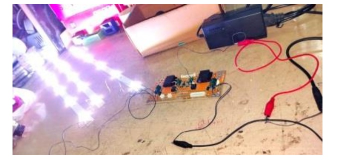
The yellow LED driver board that I used was drawing high current and therefore I did not want to use it as it might overload the PS of the TV. So I opted for an LED Driver board with its on power supply from 230V AC Mains. I connected that and checked the current drawn by the strips and the voltage:
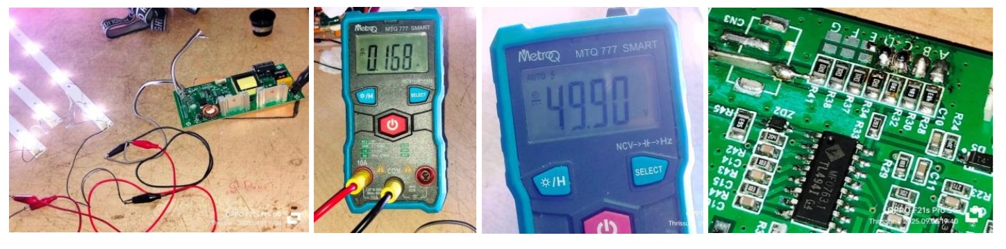
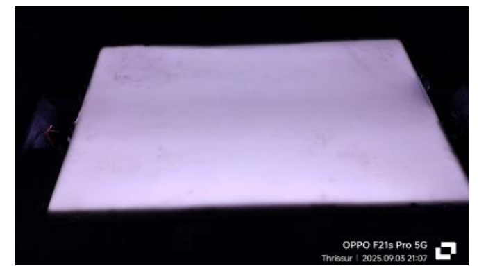
It was showing 168mA at 49.90V with a bright enough light. This inverter board had a current+voltage adjuster for which we have to short the points marked on the board, picture of which can be seen at the last above. The desired voltage was reached after I shorted three points on it. When I tried shorting the fourth one too to increase the Voltage to slightly up, the current drawn shot up to 438mA. So, I removed the fourth short. But what you see in the picture has four shorts, because I took it then. Then just kept the strips inside the oval shaped back cover, keeping one in the middle and the other two about 4” away from the middle. Since the dome on the LED spread the light around, the middle strip would take care of the central area, and the slightly angled strips would provide light to the opposite sides of the area. Then I covered the top with the diffuser sheets and found that the illumination was good enough to provide a good backlight for the panel.
The next challenge was to fix the strips in this position. I took the measurement of the oval shape from top to bottom bending the tape along the tapering, divided it by three and marked it on a discarded LED metal strip. Took one more and copied the markings. Then drilled holes in the centre to hold the strips in place. Then bent the strips exactly like the oval shape of the back cover and fixed the three strips in place. Then fixed the strips on the reflector sheet with paper tapes taking care not to puncture it. That was a delicate job and I had to be extremely careful in fixing it. The tips of the support strips were measured and cut in such a way that it would have a pressing pressure by the thick diffuser sheet kept on top to help holding it in place without moving. Let us have a look at this interesting arrangement done, which perhaps is one of the out of box thinking:
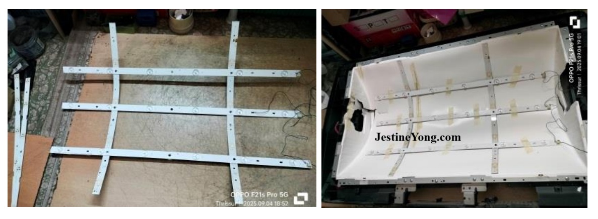
Just see, how snugly the backlight strips got fixed! I patted myself for this achievement and my techie friend also appreciated me on this innovative method employed. Since CCFL inverter board was taken out, I could place the LED driver board inside the same place. Then reassembled the diffuser sheets with its side holding frames and panel with its holding frames.
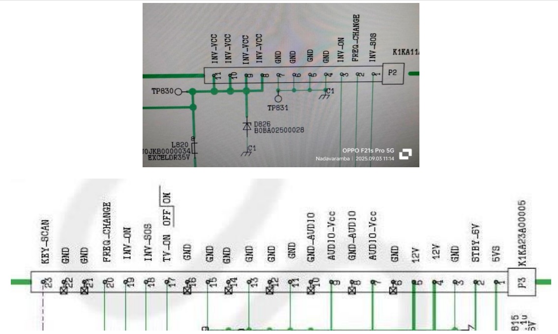
The next step was to interface the LED driver to the mother board. This TV had many number of protections employed, a list of which was shown in the service manual. One of this was inverter_SOS, which you can see in the connection diagram given. In order to check whether the inverter_SOS required a high or low, which was not mentioned in the service manual, I connected the inverter board with its lamp load externally providing two separate adaptors with a 21V for inverter and 3V for power on.
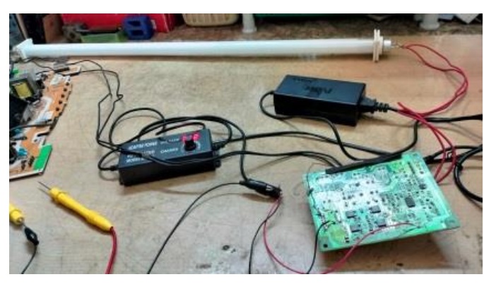
The SOS point was dropping to 0 when the lamp got on, which was good enough for me to decide what to do to fool the µController. I disconnected this testing assembly and shorted the SOS to ground on the PS board (pin 3 to ground). Then wired the LED driver properly fixing it in place with double sided tapes. Then tapped two AC in points with wires and one inverter on wire along with a ground from the PS Board. Then inserted the interconnected MB & PS boards in its slots and grooves gently, and inserted the LVDS cable when the MB reached the correct position. Then rechecked all connections and ensured that there were no mistakes. Then applied power and saw AV2 shown on the panel. There was no display on the panel like the modern TVs and the screen remained dark until the selected source connection shown. This TV shows red on power on and turns to blinking green on release from standby which becomes steady on TV on after finishing the pre-boot testing. Having satisfied with the startup, I applied a video and allowed the TV to run for some time before fixing the front and back cover. It worked for about three hours and then turned to red blinking. I counted the blinking and found it was 10 times. The service manual indicated that 10 times blinking was a 3.3V error.
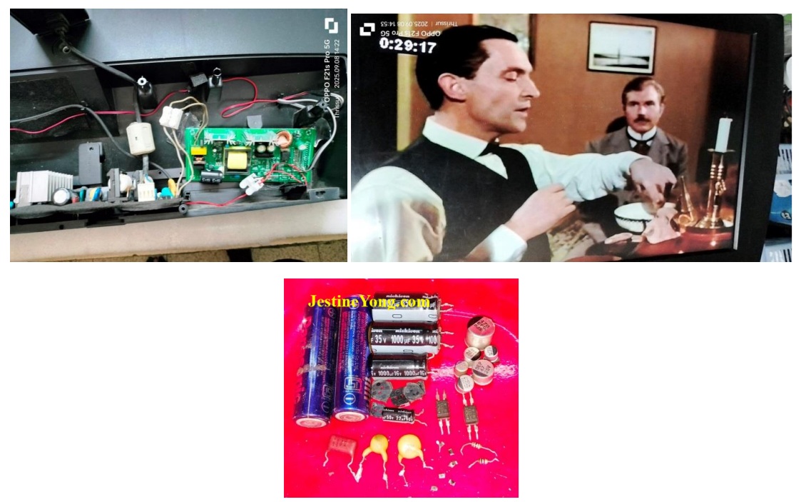
Anyhow, I had to take out the two boards again after removing the backlight connections and LVDS cable for conducting further check up. The advantage of this TV was we could power it up without connecting the panel, as the T-con was within the mother board, which I realized by chance. Since the sub-voltages were generated in the mother board, I checked the relative ICs and did not find any abnormal heat. The next possibility was filter caps used in the two 3.3V, one 1.8V and another 1.2V ICs. I replaced all the six SMD aluminium caps. Then it worked for some time again but started blinking two times, which showed error in 1.8V. During my work such as this, I kept in touch with one of my techie friends who was always very obliging, and took his directions. He asked me to check the PS out voltages and check its stability using the DSO. There indeed was a problem as the voltages were unsteady and there were disturbance pulses. So, I detached the mother board and combed the PS board thoroughly. First I replaced all the electrolytic capacitors, but the problem remained same. Instead of 21V it was varying from 15 to 17V. 12V was showing around 7.5V. Then I replaced all the resistors in the TL431 feedback circuit, as any variation on load would create such problems. I also replaced the two Opto-couplers (PC123 were replaced by 817 as advised by my techie friend.) But problem remained same. The PS used STR6766. So, I removed and checked the three fixed caps 831-2KV, 331-2KV and 103-630V and found that the values had changed. I replaced them and conducted a thorough retouch of the PS board and also the sub supplies in the MB. Then cleaned the board thoroughly and rechecked for any man made mistakes.
The PS was found working fine with the correct voltages this time. The DSO checking was also showed steady outputs.
The Voltage readings were 21.82, 12.10 and 6.13. I allowed the boards to be in on position for quite some time, after which I fixed the boards back. This time I cut the wires that went to the LED driver and provided clip on connectors so as to enable an easy removal of the boards in case of repetition of complaints. Then allowed the TV to run for several hours before fixing the back cover and front frame. Mission accomplished with a lot of sweating out that qualified for a decent entry of satisfaction to the collection bag.
P.S. The cost of service exceeded the estimate given and I had to request for a corresponding increase. As usual, I always kept the customers informed of the work done on their sets and submitted progressive reports with pictures and short videos. I have found that when we involve the customer in our work, they do not bargain when we finally put the bill. This customer was overwhelming because he paid me more than what I asked for stating that I deserved the raise for the kind of work that I did in the TV. Well, such good people are also there in this world! I thanked him profusely and prayed God to give him good health, wealth and prosperity for his kind and understanding nature!

This article was prepared for you by Parasuraman Subramanian from India. He is 76 years old and has more than 30 years’ experience in handling antique equipment like Valve Radio, Amps, Reel Tape Recorders and currently studying latest tech-classes conducted by Kerala State Electronics Technicians’ Association. He has done graduation in BBA degree, private diploma in Radio Engineering and retired as MD of a USA company. Presently working as Consultant to Hospital and other institutions.
Please give a support by clicking on the social buttons below. Your feedback on the post is welcome. Please leave it in the comments.
P.S-If you enjoyed reading this, click here to subscribe to my blog (free subscription). That way, you’ll never miss a post. You can also forward this website link to your friends and colleagues-thanks!
You may check on his previous article on No Display Problem Solved In TCL Android LED TV Model 32S5202
 (32)Dislikes
 (0)
(0)
10 Comments
Leave a Reply


Albert van Bemmelen
April 18, 2026 at 3:46 pm
Thanks for this most interesting backlight repair story Parasuraman! It sure must have been a hell of a job after so many new problems popped up before everything finally was fixed. I am not sure what parts exactly all needed to be replaced on the boards that previously were out of spec as a result. Also do not know what new LED Driver board with its on power supply from 230V AC Mains you here used because it was not mentioned? But sure can see why your wife was concerned after placing this heavy tv once again on your son’s bed! And thanks to the link to the service manual that showed a very detailed constructed guide of this Panasonic TV with its AC 110-127V, 60 Hz Maximum 100W power dissipation.
Parasuraman S
April 18, 2026 at 6:26 pm
I have already explained what all the parts that were replaced very clearly in the last portion of the article. Mainly these were filter caps and EMI filter caps. The LED driver board with power supply is commonly available in the market. But I think there was no special model or marking on the board and that's why I could not share that. I do not remember about it now. Many thanks for your expert comments, dear Albert!
Mark J
April 19, 2026 at 2:17 am
Interesting and informative article. You are a expert at TV repair. Thank you for sharing these Parasuraman.
Parasuraman S
April 19, 2026 at 8:32 am
Many thanks for your comments, dear Mark!
Yogesh Panchal
April 19, 2026 at 3:08 pm
Good job! Sir,
Congratulations!for completing complicated Task.
Parasuraman S
April 19, 2026 at 6:59 pm
Many thanks, dear Yogesh Bhai!
Imoudu.O
April 20, 2026 at 5:14 am
Few tv can be tag unserviceable on your desk,more grease to your working hands. incidentally this same hour I read this arcticle,a neighbour call me to check his lg tv,while trying to connect it to antenna,it went to red standby mode seizure!!
Thanks for sharing sir.
Parasuraman S
April 21, 2026 at 2:00 pm
Good to know! Let more and more chances get bestowed! Many thanks for your lovely comments, dear Imoudu! Distance only makes relationships closer, because of the benevolence shown by our beloved Jestine Yong, who continues to let us contribute! May God bless one and all!
Muykit
April 20, 2026 at 3:01 pm
What an elaborative article for purposes of ease of understanding. Your kind is, one out of millions. Above all, thanks. When working on LED lights, regardless of the item, isnt current flow control managed by a suitable series resistor to cushion the vulnerable LEDs ?
Parasuraman S
April 22, 2026 at 7:39 pm
Yes indeed, it is managed by series of resistors. Many thanks!